
User guide

USER GUIDE
8
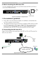
6. Rack mounting the DX User IP II
Use the L-shaped brackets and screws provided to mount the DX User IP II on a
server rack as illustrated below.
Insert
screws to
connect to
rack
Insert screws to connect
to DX User IP side panel
POWER
100-240 VAC 50/60 Hz
ww w. mi ni co m .co m
ETHERNET
SERIAL
I
0
SYSTEM
USB TERMINAL
USER
RST
Figure 4 Connecting the L-shaped brackets
7. Pre-installation guidelines
· Place cables away from fluorescent lights, air conditioners, and machines that
are likely to generate electrical noise
· The maximum distance between each device (computer, KVM switch or second
level DX Central) and the DX Central is 100m/330ft. The maximum distance
between the DX Central and the DX User IP II is also 100m/330ft. For best
performance place the DXU IP II as close as possible to the DX Central.
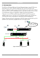
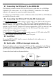
8. Connecting the DX User IP II
Figure 5 below illustrates the connections of the DX User IP to the DX system. See
below for more details.
POWER
100-240 VAC 50/60 Hz
www.min icom.c om
ETHERNET
SERIAL
I
0
SYSTEM
USB TERMINAL
USER
GO LOCK
SERIAL 2
SD
P110
CAT5
cable
To DX Central
User port
Internet / VPN / LAN
Remote user
(Optional)
Local
User
console
Figure 5 DX User IP connections