
User guide

DX USER IP II
7
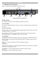
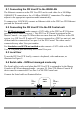
5.1 DX User IP II rear panel
Figure 3 illustrates the rear panel of the DX User IP II.
Power
connector
RS232 Serial
port
POWER
100-240 VAC 50/60 Hz
www.minicom.com
Go Lock
button
Ethernet
port
ETHERNET
SERIAL
I
0
SYSTEM
Keyboard
Mouse
Monitor
USB TERMINAL
USER
USB
ports
RS232
Terminal port
CAT5 to DX
Central
GO LOCK
DX Reset
button
SERIAL 2
Serial 2
port
Figure 3 DX User IP II rear panel ports
DX Reset button
The DX Reset button resets the DX parts of the DX User IP II.
Go Lock button
The Go Lock button disconnects the active remote session and returns control to the
local user.
Serial / Serial 2 port
The Serial port is only used for KVM.net managed mode when the DX User IP II is
the Master Console – see page 30.
In Standalone and KVM.net enable modes, the Serial 2 port can be used for any
RS232 application, e.g. managing a router or power switch.
Terminal port
In Standalone and KVM.net enable modes only, when there are X-RICC RS232s in
the DX system, you can control them through an RS232 terminal connected to the
DX User IP II.
Ethernet - Connects the DX User IP II to an Ethernet network.
USB ports
Update the DX firmware via a Minicom Flash USB key. See the DX User Guide for
information on updating firmware.
System port – Used to connect the DX User IP II to the DX Central.
KVM ports – Used for optional local console.