DX User IP II User Guide w w w . m i n i c o m . c o m International HQ North America Jerusalem, Israel Linden, NJ, USA Tel: + 972 2 535 9666 minicom@minicom.com Tel: + 1 908 486 2100 info.usa@minicom.com Technical support - support@minicom.com SC_5UM60000 V1.
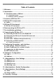
DX USER IP II Table of Contents 1. Welcome ................................................................................................................ 3 2. Introduction ........................................................................................................... 4 2.1 Standalone mode or KVM.net ......................................................................................5 2.1.1 Standalone mode.......................................................................................
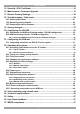
USER GUIDE 15. Security > SSL Certificate ................................................................................ 19 16. Maintenance > Firmware Upgrade .................................................................. 19 17. Restore Factory Settings ................................................................................. 20 18. Troubleshooting - Safe mode .......................................................................... 20 18.1 Entering Safe mode ................................
DX USER IP II 1. Welcome Thank you for buying the DX User IP II system. The DX User IP II system is produced by Minicom Advanced Systems Limited. Technical precautions This equipment generates radio frequency energy and if not installed in accordance with the manufacturer’s instructions, may cause radio frequency interference. This equipment complies with Part 15, Subpart J of the FCC rules for a Class A computing device.
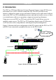
USER GUIDE 2. Introduction The DX User IP II from Minicom Advanced Systems features remote KVM access and control via a LAN or Internet connection. DX User IP II provides a nonintrusive solution for remote access and control. Remote access and control software runs on the DX User IP II embedded processors only and not on the servers, so there is no interference with server operation or impact on network performance.
DX USER IP II 2.1 Standalone mode or KVM.net DX User IP II can be used in any of the following 3 modes: · Standalone · KVM.net enabled · KVM.net managed KVM.net is a centralized IP based system for secure control of servers and network devices, power and user administration in the data center environment. KVM.net combines Out-Of-Band, KVM via IP access with modern IT standards and requirements. It is the most comprehensive remote server maintenance solution available in the market today.
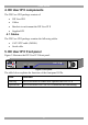
USER GUIDE 4. DX User IP II components The DX User IP II package consists of: · DX User IP II · Cables · Brackets to rack mount the DX User IP II · Supplied CD 4.1 Cables The DX User IP II package contains the following cables. · CAT5 FTP cable (2M/6Ft) · Serial cable 5. DX User IP II front panel Figure 2 illustrates the DX User IP II front panel. MINICOM DXU - IP II Activity System OK Figure 2 Front panel The table below explains the functions of the front panel LEDs.
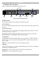
DX USER IP II 5.1 DX User IP II rear panel Figure 3 illustrates the rear panel of the DX User IP II. USB ports www.minicom.com Power connector Monitor SERIAL I 0 POWER 100-240 VAC 50/60 Hz RS232 Serial port SYSTEM CAT5 to DX Central USB DX Reset button TERMINAL USER GO LOCK Go Lock button RS232 Terminal port SERIAL 2 ETHERNET Serial 2 Ethernet port port Mouse Keyboard Figure 3 DX User IP II rear panel ports DX Reset button The DX Reset button resets the DX parts of the DX User IP II.
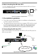
USER GUIDE 6. Rack mounting the DX User IP II Use the L-shaped brackets and screws provided to mount the DX User IP II on a server rack as illustrated below. www.minicom.com SERIAL I 0 Insert screws to connect to rack USER RST SYSTEM POWER 100-240 VAC 50/60 Hz USB TERMINAL ETHERNET Insert screws to connect to DX User IP side panel Figure 4 Connecting the L-shaped brackets 7.
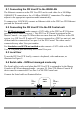
DX USER IP II 8.1 Connecting the DX User IP to the WAN/LAN The Ethernet connector on the DX User IP II can be used either for a 100 Mbps 100BASE-TX connection or for a 10 Mbps 10BASE-T connection. The adapter adjusts to the appropriate operation mode automatically. To connect to a LAN/WAN, connect an Ethernet cable to the DX User IP II Ethernet port and the Network switch. 8.2 Connecting the DX User IP II to the DX Central unit For KVM.
USER GUIDE 8.5 Connecting an RS232 terminal Connect the RS232 terminal to the DX User as illustrated in the figures below. www.minicom.com SERIAL I 0 POWER 100-240 VAC 50/60 Hz SYSTEM USB TERMINAL USER GO LOCK SERIAL 2 ETHERNET To Terminal port Terminal Login: admin Password_| d i g i t a l VT420 Contrast Bright Figure 7 Connecting the RS232 terminal 8.5.1 Order of powering on Connect the DX User IP to the power supply using the power cord provided.
DX USER IP II Note! If a DHCP server later becomes available, the unit picks up the IP settings from DHCP server. To keep the static IP address, disable DHCP – explained in section 10.1 on page 13. 9.
USER GUIDE Figure 9 DXU IP II Web interface 5. Bookmark the page for easy reference. 9.4 SSL Certificate notes When first connecting to DXU IP II’s https configuration page, 2 browser security warnings appear. Click Yes to proceed. The first warning disappears upon first DXU IP II client installation, when Minicom’s root certificate is installed. 10. Network > Configuration Consult your Network Administrator for the network settings. Device name - Type a name for the DXU IP II.
DX USER IP II 10.1 LAN 1 Under LAN 1 in Figure 9, is the following: Enable DHCP – When a DHCP server is active on the same network to which DXU IP II is connected, DHCP provides automatic IP assignment. When DHCP is disabled – (Recommended) – You can assign a fixed IP address to the DXU IP II. Consult your Network Administrator regarding the use of the DHCP.
USER GUIDE 11. Administration > User Settings Note! This section is only relevant to Standalone mode. From the menu click User Settings, Figure 10 appears. Figure 10 User Settings Although there are Users in the DX system created in the AIM interface, these can only access the system locally. To access the system over IP, you must create Users in the web interface. On this page an Administrator creates and edits users.
DX USER IP II 11.1 Adding a user To add a user: 1. Click and type a name and a password. The password must be at least 6 characters – letters or numbers, and must not include the user name, even if other characters are added. Note! The following “special” characters: &, <, >, ”, {, } cannot be used for either the user name or password. Depending on the security level chosen the user name and password parameters are different. See section 14 on page 18. 2. Select the permission type from the Permission box.
USER GUIDE 12. Administration > Switch Configuration Note! This section is only relevant to Standalone mode. 1. From the menu click Switch Configuration. The Switch Configuration window appears, see Figure 11. Figure 11 Switch Configuration 2. From the Manufacturer drop-down list select Minicom. 3. From the Model drop-down list select the DX system according to the number of Central units in the system – 32 ports for 1 Central unit, 64 ports for 2 Central units etc.
DX USER IP II 13. Administration > Serial Settings Note! This section is only relevant to Standalone mode. Where you have a Serial device connected to the DXU IP II you must configure the RS232 settings. To do so: From the menu click Serial Settings, the Serial Settings appear, see Figure 12. Figure 12 Serial Settings Type a device name and choose the correct device parameters. Note! Where you have a Minicom Serial Remote Power Switch connected, see below Assign to RPS. 13.
USER GUIDE 14. Security > Settings Note! This section is only relevant to Standalone mode. Configure the security features, such as Account Blocking, Password Policy and Idle Timeout, as explained below. From the Security section click Settings, the Security Settings appear, see Figure 13. Figure 13 Security Settings The Security Settings fields: Account Blocking – decide on the number of attempts to login with a wrong username or password after which there is a time lock or a total block.
DX USER IP II 15. Security > SSL Certificate Note! This section is only relevant to Standalone mode. You can install an SSL certificate. To do so: From the menu, select SSL Certificate, the install SSL Certificate page appears, see Figure 14. Figure 14 Install SSL Certificate page Certificate File - Browse to locate the cer file. Private File - Browse to locate the private key file. Key Password - Type the “private key” password. 16.
USER GUIDE Note! Depending on the type of firmware upgrade, the following settings may be erased: User settings, server names, mouse and video adjustments. For more information refer to the firmware release notes. The network settings remain intact. 17. Restore Factory Settings You can restore the DXU IP II unit to the factory settings.
DX USER IP II 18.1 Entering Safe mode To enter Safe mode: 1. Press and hold down the Go Lock button for 3-4 seconds and at the same time power up the DXU IP II. The device boots up in Safe mode. 2. Wait until the unit finishes booting (1-2 minutes). 3. You need to know the IP address of the DXU IP II. The IP address depends on whether there is a DHCP server on the network. If there is, the DHCP server assigns an IP address to the DXU IP II.
USER GUIDE 18.2 Restoring factory defaults To restore factory defaults: 1. From the menu choose Restore Factory Settings. A warning appears see Figure 19. Figure 19 Warning 2. Click . A further warning appears, see below. Figure 20 Warning 3. Click OK, the factory defaults are restored. When the process finishes Figure 21 appears. Figure 21 Reboot 4. Click Reboot to restart the unit. 18.3 Restoring the device firmware Contact Minicom Technical Support support@minicom.
DX USER IP II Figure 22 Reboot 3. Click Reboot to restart the unit. 19. Saving changes Click to save configuration changes and restart the DXU IP II. Only one Administrator can log into the Configuration area at a time. An idle timeout of 30 minutes terminates the session. For Standalone and KVM.net enabled and managed modes the DX AIM needs to be configured, see the next section. 20.
USER GUIDE On connection, the DX AIM appears, see Figure 24. Figure 24 shows the Servers page already configured with a number of servers. If the DX system has never been configured, the Servers page appears blank. To configure/manage the DX system, see the DX User Guide.
DX USER IP II 20.1 Standalone and KVM.net Enabled modes - DX AIM configuration For KVM.net managed mode, go to section 20.2. From the Tools menu click Settings, the Settings window appears. See Figure 25. Figure 25 Settings window In Settings, ensure that Direct Hotkey is set to CTRL-CTRL (default). In Extensions, select Enable Direct Connection and Use consistent hotkey. To save changes click File/Save changes, or . 20.2 KVM.
USER GUIDE Input ports to DX User units Output ports to devices List of DX Central units and other KVM switches Information about currently selected switch Figure 26 DX System Configuration window The above figure shows the rear ports of a DX Central unit, including the DX User units. 2. Click a DX User unit. The Configuration box appears, see Figure 27. Figure 27 Configuration box 3. Select the Managed by KVM.net checkbox. 4. Click OK. Once a DX User unit is KVM.
DX USER IP II 20.2.1 Accessing AIM when the DX system is KVM.net managed When the DX is KVM.net managed when attempting to access the AIM interface, it does not appear. Instead the screen appears black with a message stating that the DX system is KVM.net managed. To access the AIM (to e.g. disable the KVM.net managed mode): 1. From a remote computer console type the DXU IP II’s IP address. You connect to one of the servers in the DX system. 2. Press left Shift, Shift.
USER GUIDE Figure 28 KVM Switches page 2. For KVM.net enabled select the correct DX configuration with Ctrl (and not PRT-SCR hotkey). For example when there is 1 DX Central unit in the DX system, select Minicom DX System (32 ports Ctrl). When there are 2 DX Central units in the DX system select Minicom DX System (64 ports Ctrl). For KVM.net managed select the correct DX configuration with PRT-SCR (and not Ctrl hotkey).
DX USER IP II Figure 29 Devices page 4. Double-click the DXU IP II device. The Device Properties General tab appears, see Figure 30. Figure 30 Device Properties General tab 5. In the name field give the device a unique name. 6. Click the KVM Switch tab, the following appears.
USER GUIDE Figure 31 KVM Switch tab 7. In the KVM Switches field select as follows: For KVM.net enabled select the correct DX configuration with Ctrl (and not PRT-SCR hotkey), as selected in the KVM Switches page see page 28 above. For KVM.net managed select the correct DX configuration with PRT-SCR (and not Ctrl hotkey), as selected in the KVM Switches page see page 28 above. Once the correct DX configuration with PRT-SCR is selected, the KVM Switch tab appears as in Figure 32.
DX USER IP II 21.1 Connecting more than one DXU IP II to the system When there are more than one DXU IP II units in the system you must do the following: 1. Select the KVM switch file for all DXU IP II units. So follow steps 3 – 7 above for each DXU IP II unit. 2. In Device Properties click the Targets tab, see Figure 33. Here you assign the Target servers to the specific ports of the DXU IP II unit. You must assign the same Targets to the same ports for each DXU IP II unit. 3.
USER GUIDE 22. Operating the system How to operate the system depends on how the DX User IP II is being used – Standalone, KVM.net enabled or KVM.net managed. · For Standalone, operation is only via the IP toolbar · For KVM.net enabled, operation is via the IP toolbar or KVM.net Manager · For KVM.net managed, operation is via the IP toolbar or KVM.net Manager The sections below explain how to operate the system for each mode. 22.
DX USER IP II To display the Toolbar repeat the above actions. See also page 43. 22.1.2 Accessing a server/device To connect to a server/device: Important! Accessing or switching to the servers from the IP toolbar only works when the DX AIM is on the Servers/Devices page, see Figure 24. 1. Select View/Servers/Devices to display the Servers/Devices page. , or right-click . A list of connected 2. From the Toolbar, click servers/devices the user has permission to access appears.
USER GUIDE Target server name Toolbar icon Remote screen border Minicom icon Figure 34 Remote console window On the remote console you have the following: Target server name - The currently accessed server identity can be checked by looking at the Server name on the Internet Explorer title bar. Toolbar icon – This is the minimized toolbar from which you switch and configure the system. Minicom icon – Hold the mouse over the icon to view information about current server, connection time and video mode.
DX USER IP II Figure 35 Busy remote session options Choose to Take Over or View Only or Cancel. When watching a screen in View Only mode you can Double click inside the Remote screen border – see Figure 23 – to take over the remote control. The current user sees a message stating that control has been taken over. 22.3 Full screen mode Work on the Target Server as if you are working on a local computer, with full screen mode. To work in full screen mode: 1.
USER GUIDE Figure 36 Settings.. box Bandwidth Choose from the following options: Adaptive – automatically adapts to the best compression and colors. Low - Select Low for high compression and 16 colors. Medium - Select medium for medium compression and 256 colors. Medium is recommended when using a standard internet connection. High - For optimal performance when working on a LAN, select High. This gives a low compression and high colors (16bit).
DX USER IP II 22.5.2 Manual Video Adjust Use the manual video adjustment for fine-tuning the Target Server video settings after auto adjustment or for adapting to a noisy environment or a non-standard VGA signal or when in full-screen DOS/CLI mode. To adjust the video manually: 1. Click Manual Video Adjust. A slider bar appears. See Figure 37. Also a red frame appears around the screen. This represents the screen area according to the Server's screen resolution.
USER GUIDE 22.5.3 Auto Video Adjust To adjust the video automatically: We recommend opening Windows Explorer (or similar) in the background. Click Auto Video Adjust. The process takes a few seconds. If the process runs for more than 3 times, there is an abnormal noise level. Check the video cable and verify that no dynamic video application is running on the Target Server’s desktop. Perform the procedure where necessary for each Target Server or new screen resolution. 22.
DX USER IP II Figure 39 Special Key Manager box To add a predefined sequence: 1. Click Add Predefined. A list of sequences appears. 2. Select the desired sequence and click OK. The sequence appears in the Special Key Manager box. 3. Click OK. The sequence appears in the Keyboard Key sequence list. To record a key sequence: 1. From the Special Key Manager box press Record New. The Add Special Key box appears see Figure 40. Figure 40 Add Special Key box 2. Give the key sequence a name in the Label box. 3.
USER GUIDE To edit a key sequence: 1. From the Special Key Manager box select the desired key. 2. Click Edit. 3. Click Start Recording 4. Press the desired keys. The keys appear in the area provided. 5. Click Stop Recording. 6. Click OK. 22.8 Synchronizing mouse pointers When working at the Client computer, two mouse pointers appear: The Client computer’s is on top of the Target Server’s. The mouse pointers should be synchronized. The following explains what to do if they are not synchronized.
DX USER IP II If the Video Noise Level is above zero, calibration may not work. Go to Video Adjustment and try to eliminate the noise by pressing Auto video adjust and/or adjusting the bars in Manual video adjust, then perform the mouse calibration. Note! If the mouse settings on the Target Server were ever changed, you must synchronize mouse pointers manually, as explained below. 22.8.3 Manual mice synchronization Only in Standalone mode. (For KVM.
USER GUIDE 2 examples! For Windows XP, go to the Mouse settings on the Target Server and uncheck Enhance pointer precision. For Windows NT4. If Mouse Properties were ever changed for the Target Server – even if they have been returned to their original state - uncheck default . Click OK. The mouse pointers should be synchronized. USB The USB option in Mouse Settings box is available for X-RICC USB and for unsupported operating systems and SUN Solaris.
DX USER IP II 22.9 Minicom logo menu features Right click the Minicom logo , a menu appears. From this menu you can access the connected devices. You also have the following features: Disconnect – You can disconnect the session by clicking Disconnect. About - Click About to verify the Client, Firmware, KME (Keyboard/Mouse Emulation firmware) and Switch file versions installed on your DXU IP II. Local Settings – Click Local settings, the Client Configuration box appears, see Figure 43.
USER GUIDE 22.10 Disconnecting the remote session To disconnect the remote session: On the Toolbar, click . For KVM.net managed mode the User disconnects from the server and from the remote session. For Standalone and KVM.net enabled modes the User disconnects from the server and from the remote session. The DXU IP II remains logged into the AIM. You can download and install an SDF (RPC extension file), which when clicking will disconnect from the Server, the remote IP session and the DX AIM.
DX USER IP II 23. Video resolution and refresh rates The DX User IP II supports the following video modes. Do not use other custom video settings.
USER GUIDE 24. Technical specifications Target Server DOS, Windows, Novell, Linux, SUN Solaris Unix Operating systems Client Computer Windows 2000 or higher with IE 6.0 or higher and Installation of signed ActiveX controls must be enabled in the Client computer.
DX USER IP II 25. Safety The device must only be opened by an authorized Minicom technician. Disconnect device from AC mains before service operation! 26. User Guide feedback Your feedback is very important to help us improve our documentation. Please email any comments to: ug.comments@minicom.com Please include the following information: Guide name, part number and version number (as appears on the front cover). 27.