
User Guide switch DX System
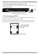
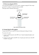
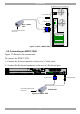
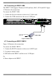
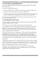
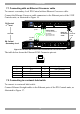
Table Of Contents
- Welcome
- 1. Introduction
- 2. Pre-installation guidelines
- 3. DX system outline
- 4. Connecting the DX system
- 4.1 Connecting an optional local computer to a DX User
- 4.2 Connecting servers to the DX Central
- 4.3 XRICC power supply
- 4.4 Connecting a RICC or XRICC PS/2
- 4.5 Connecting an XRICC SUN
- 4.6 Connecting an XRICC USB
- 4.7 Connecting an XRICC RS232
- 4.8 Connecting the CAT5 cables
- 4.9 Connecting the DX User to an RS232 Terminal
- 5. Power management
- 6. Connecting Legacy KVM switches
- 7. Cascading DX Central units
- 8. Powering on the system
- 9. Configuration wizard (non-DX cascaded system)
- 10. Logging in
- 11. Configuring the DX system
- 12. Creating/editing Users and Groups
- 13. Arranging devices
- 14. Scanning a group of servers
- 15. Adjusting the picture quality
- 16. Connect - Private
- 17. Disconnect User
- 18. Connecting to a local computer
- 19. Updating the DX Central
- 20. Updating the DX User and XRICCS/RICCs
- 21. Events log
- 22. Troubleshooting - Resetting the DX Central
- 23. USB / SUN Combo keys
- 24. Technical specifications
- 25. Terminal hotkeys
- 26. User guide feedback
DX SY
STEM
19
7.1 Connecting with an Ethernet Crossover cable
To connect a secondary level DX Central with an Ethernet Crossover cable:
Connect the Ethernet Crossover cable connectors to the Ethernet ports of the 2 DX
Centrals units, as illustrated in Figure 16.
POWER
www.min icom.com
ETHERNET
SERIAL
SERVICEI
0
1234
18192017
SERVER
5678
22232421
1234
6785
9101112
26272825
13141516
30313229
USER
POWER
www.minicom .com
ETHERNET
SERIAL
SERVICE
I
0
1234
18192017
SERVER
5678
22232421
1234
6785
9101112
26272825
13141516
30313229
USER
DX Central
- 1
st
level
DX Central
- Secondary level
Cascade
To User
ports
To Server
ports
Ethernet
Crossover
cable
CAT5 cables
1 for each DX User in
the system
Up to 8 for 8 x 32
Up to 4 for 4 x 32
To
Ethernet
ports
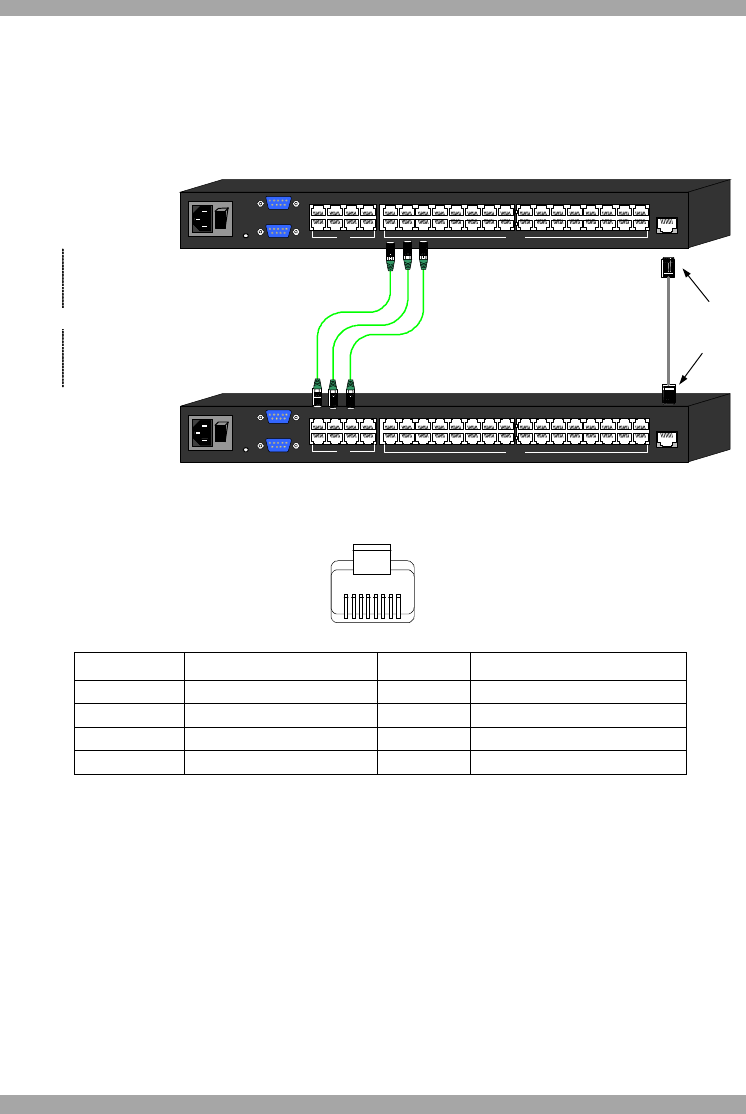
Figure 16 Cascaded DX Central units connected with a Crossover cable
The table below shows the Ethernet RJ 45 Connector pin-out.
1
8
Pin Assignment Pin Assignment
1 TX + 5 Not connected
2 TX - 6 RX -
3 RX + 7 Not connected
4 Not connected 8 Not connected
7.2 Connecting to a network hub/switch
To connect to a network hub/switch:
Connect Ethernet Straight cables to the Ethernet ports of the DX Centrals units, as
illustrated in Figure 17.