
User Guide switch DX System
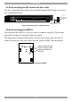
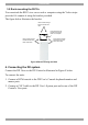
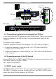
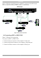
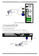
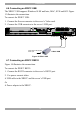
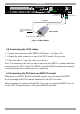
Table Of Contents
- Welcome
- 1. Introduction
- 2. Pre-installation guidelines
- 3. DX system outline
- 4. Connecting the DX system
- 4.1 Connecting an optional local computer to a DX User
- 4.2 Connecting servers to the DX Central
- 4.3 XRICC power supply
- 4.4 Connecting a RICC or XRICC PS/2
- 4.5 Connecting an XRICC SUN
- 4.6 Connecting an XRICC USB
- 4.7 Connecting an XRICC RS232
- 4.8 Connecting the CAT5 cables
- 4.9 Connecting the DX User to an RS232 Terminal
- 5. Power management
- 6. Connecting Legacy KVM switches
- 7. Cascading DX Central units
- 8. Powering on the system
- 9. Configuration wizard (non-DX cascaded system)
- 10. Logging in
- 11. Configuring the DX system
- 12. Creating/editing Users and Groups
- 13. Arranging devices
- 14. Scanning a group of servers
- 15. Adjusting the picture quality
- 16. Connect - Private
- 17. Disconnect User
- 18. Connecting to a local computer
- 19. Updating the DX Central
- 20. Updating the DX User and XRICCS/RICCs
- 21. Events log
- 22. Troubleshooting - Resetting the DX Central
- 23. USB / SUN Combo keys
- 24. Technical specifications
- 25. Terminal hotkeys
- 26. User guide feedback
DX SY
STEM
17
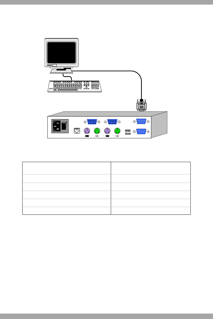
4.9.1 Connecting the RS232 terminal
Connect the RS232 terminal to the DX User as illustrated in the figures below.
TO CENTRAL
POWER
100-250 VAC 50/60 Hz
www .m i ni co m.c o m
I
0
USB
LOCAL COMPUTER
TERMINAL
CONSOLECOMPUTER
To
Terminal
port
Terminal
VT420
ContrastBright
digital
Login: admin
Password_|
Figure 15 Connecting the RS232 terminal
The table below shows the RS232 Serial cable 9 PIN D-SUB Male pin-out.
Pin Signal Description Pin Signal Description
1
CD
Carrier Detect 6 DSR Data Set Ready
2 RxD Receive Data 7 RTS Request to Send
3 TxD Transmit Data 8 CTS Clear to Send
4 DTR Data Terminal Ready 9 RI Ring Indicator
5 GND System Ground
5. Power management
You can connect a Power management device to the DX Central; the DX Users can
then power devices on and off.
Connect the Power management device to the Serial port of the DX Central using
the Serial cable provided with the Power management device.
Connect the Power management device to each device by following the instructions
in the Power management device User Guide.