
User guide


DX POWER SWITCH 8 PORT
5
6. Assigning ID numbers
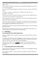
Assign an ID number to each Slave by positioning the dipswitches marked Slct on
the front panel according to the following table.
Unplug the device before changing its dipswitches.
Do NOT use the same address for two different Slaves.
ID number Dipswitch 1 Dipswitch 2
1 Off Off
2 On Off
3 Off On
4 On On
Position Off = switch upwards
Position On = switch downwards
Micro-switch 1 is on the left side, micro-switch 2 on the right.
Plug the 2 power cables into grounded sockets. The A and B LEDs illuminate to
confirm that power is on.
7. Configuring the DX Power Switch-Standalone
To use the switch on your network you must first configure its network parameters.
Ask your Network administrator for the Network parameters to use.
There are 2 configuration methods.
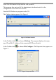
Method 1 - Through a Network using the DX Power Switch Finder Utility (on the
CD).
Method 2 - Through a RS232 Serial connection using a Terminal connection. See
page 8.
Method 1
It is simple and fast if you use a Windows operating system. We recommend using
this program for the first configuration. With it you can configure your DX Power
Switch-Standalone through a local Network even if its network parameters (IP
Address, Subnet mask and Port) are not compatible with those of your PC or your
local network.
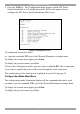
The DX Power Switch-Standalone and the PC used to configure it must be
connected on the same segment of the network and not through a WAN or the
Internet.