
User guide


USER GUIDE
4
The DX Power Switch devices can only be connected to three-wire 230 VAC (50-
60Hz) sockets.
Always plug the DX Power Switch devices into properly grounded power sockets
(two poles plus ground).
Never exceed 10 Amp total load for each group of 4 power sockets of a DX Power
Switch.
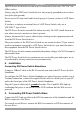
If you have to replace an external fuse of a DX Power Switch, only use a
10A/250V T type of fuse.
The DX Power Switch is intended for indoor use only. Do NOT install them in an
area where excessive moisture or heat is present.
Always disconnect the 2 power cables before working on the equipment powered
from the DX Power Switch device.
The power outlets of the DX Power Switch are not circuit breakers! If you want to
work on equipment connected to a DX Power Switch device you must disconnect
this equipment from the DX Power Switch device.
The DX Power Switch contains potentially hazardous voltages. Do NOT attempt to
disassemble them.
The DX Power Switch devices contain no user serviceable parts and repairs are to
be performed by factory trained service personnel only.
4. Installation
Connecting DX Power Switch-Standalone
Connect a 10BaseT cable to the RJ-45 network port and to the DX Power Switch-
Standalone.
To configure the DX Power Switch-Standalone or control its power sockets over a
Terminal connection, connect the supplied Serial cable to a Serial port on your PC
and to the Serial port of the DX Power Switch-Standalone.
Plug the 2 power cables into 2 grounded sockets. The A and B LEDs light up
confirming that power is on and the Power LED confirms that the Web server is
powered.
5. Connecting DX Power Switch-Slave
Connect the RJ9 Link-up cable to the RJ9 Out connector of the Standalone and the
RJ9 In connector of the Slave.
To cascade several Slaves, connect the RJ9 Out connector to RJ9 In connector of
the next Slave.