DX Power Switch - 8 Port User Guide w w w . m i n i c o m . c o m International HQ North American HQ European HQ Jerusalem, Israel Linden, NJ, USA Dübendorf, Switzerland Tel: + 972 2 535 9666 minicom@minicom.com Tel: + 1 908 486 2100 info.usa@minicom.com Tel: + 41 44 823 8000 info.europe@minicom.com Technical support - support@minicom.com 5UM20132 V1.
DX POWER SWITCH 8 PORT Table of Contents 1. 2. 3. 4. 5. 6. 7. 8. 9. 10. 11. 12. 13. 14. Welcome........................................................................................................ 2 Introduction................................................................................................... 3 Pre-installation guidelines ............................................................................ 3 Installation...........................................................................
USER GUIDE 1. Welcome The DX Power Switch 8 Port system is produced by Minicom Advanced Systems Limited. Technical precautions This equipment generates radio frequency energy and if not installed in accordance with the manufacturer’s instructions, may cause radio frequency interference. This equipment complies with Part 15, Subpart J of the FCC rules for a Class A computing device.
DX POWER SWITCH 8 PORT 2. Introduction The DX Power Switch 8 Port from Minicom is a power management system consisting of 2 units. The DX Power Switch-Standalone can be used as a stand-alone device to control over IP, 8 IEC power sockets. The number of controlled sockets can be extended to 16, 24, 32 or 40 by cascading 1 to 4 DX Power Switch-Slave.
USER GUIDE The DX Power Switch devices can only be connected to three-wire 230 VAC (5060Hz) sockets. Always plug the DX Power Switch devices into properly grounded power sockets (two poles plus ground). Never exceed 10 Amp total load for each group of 4 power sockets of a DX Power Switch. If you have to replace an external fuse of a DX Power Switch, only use a 10A/250V T type of fuse. The DX Power Switch is intended for indoor use only.
DX POWER SWITCH 8 PORT 6. Assigning ID numbers Assign an ID number to each Slave by positioning the dipswitches marked Slct on the front panel according to the following table. Unplug the device before changing its dipswitches. Do NOT use the same address for two different Slaves. ID number Dipswitch 1 Dipswitch 2 1 Off Off 2 On Off 3 Off On 4 On On Position Off = switch upwards Position On = switch downwards Micro-switch 1 is on the left side, micro-switch 2 on the right.
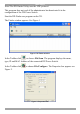
USER GUIDE Note! The DX Finder Utility uses the UDP protocol. This program does not work if the administrator has deactivated it in the configuration of the DX Power Switch. Start the DX-Finder.exe program on the CD. The Finder window appears. See Figure 1 Figure 1 DX Finder window In the Toolbar click or choose File/Scan. The program displays the name, type, IP and MAC Address of the connected DX Power Switch. In the Toolbar click Figure 2. or choose File/Configure.
DX POWER SWITCH 8 PORT Configure the Network parameters. The default Network parameters are as follows: IP address 192.168.100.100 Subnet mask 255.255.255.0 Gateway No address Port 80 To configure all other parameters, click . General Tab Define all the Network parameters of the DX Power Switch-Standalone (IP Address, Subnet Mask, Default Gateway and Port Number). Permit or deny the configuration using the DX Power Switch Finder program for security reasons.
USER GUIDE Security Tab Type addresses which are authorized or denied access to the DX Power Switch over the Network. For details about these features, see section 9 on page 17. Options Tab Define the restart delay valid for all power sockets of all DX Power Switch connected together. Configure an Email address to which the user can send a message in case of problems.
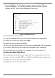
DX POWER SWITCH 8 PORT 5. Press the TAB key. The Configuration menu appears and the DX Power Switch-Standalone is in Configuration mode. Follow the menu below to configure the DX Power Switch-Standalone Web server. Figure 3 Configuration menu All commands start with a slash /. ex.: type the command /NP to go to the Network Parameters settings menu. To display the current menu again, press Enter. To display the previous menu, press Esc. To leave the Configuration mode, type the restart command /RS.
USER GUIDE Network Parameters Settings Menu Command /NP This menu is used to configure all Network parameters (IP Address, Subnet Mask, Gateway and Port) and to permit or prevent the configuration over a local area network using the DX Power Switch Finder program. NETWORK PARAMETERS SETTINGS 1. 2. 3. 4. 5. MAC Address IP Address Subnet Mask Gateway Port Finder 00.01.9A.F1.00.0F 192.168.100.100 255.255.255.0 0.0.0.
DX POWER SWITCH 8 PORT Command 4 NETWORK PARAMETERS SETTINGS Port is: 80 Enter port or to exit You must restart the device (Command /RS) to valid the new parameters > Command 5 NETWORK PARAMETERS SETTINGS Finder is: Activated 1. Activate 2.
USER GUIDE Command 2 DEVICE 1 / USERS SETTINGS 1. 2. 3. 4. 5. 6. 7. 8. User User User User User User User User 1 2 3 4 5 6 7 8 Enter Selection or to exit > Command 1 DEVICE 1 / USER 1 SETTINGS 1. 2. 3. User 1 Name User 1 Password User 1 authorized Sockets user1-1 user1-1 1,5 Enter Selection or to exit > Group, Device And Socket Names Settings Command /NS This Menu is used to assign a label to: · A group of DX Power Switches · Each DX Power Switch device · Each power socket.
DX POWER SWITCH 8 PORT Command 1 GROUP NAME SETTING Group Name is: Device Name Enter Name (max. 32 characters) or to exit > Command 2 to 6 DEVICE 1 / SOCKET NAMES SETTINGS 1. 2. 3. 4. 5. 6. 7. 8. 9.
USER GUIDE 3. 4. 5. 6. Device Device Device Device #2 #3 #4 #5 Activated Not Activated Not Activated Not Activated Twin Mode Single Mode Single Mode Single Mode Enter Selection or to exit > Command 1 MAIL TO SETTING Mail to is: Enter Name (max. 32 characters) or to exit > DEVICE 1 PARAMETERS SETTINGS Device #1 1. 2. Activated Twin Mode Single Mode / Twin Mode Activate / Deactivate Enter Selection or to exit > Command 1 DEVICE 1 PARAMETERS SETTINGS Mode is: Twin Mode 1. 2.
DX POWER SWITCH 8 PORT SOCKET RESTART DELAY SETTINGS 1. Delay before Restart (sec) 5 Enter Selection or to exit > Command 1 SOCKET RESTART DELAY SETTINGS Delay before Restart (sec) is: 5 1. 2. 3. 4. 5. 5 10 15 30 60 sec sec sec sec sec Enter Selection or to exit > Command 1 SOCKET RESTART DELAY SETTINGS 1.
USER GUIDE Command 1 IP SECURITY SETTINGS Mask #1 1. 2. 3. 0.0.0.0 Deny Not Activated Edit the Mask Permit / Deny Activate / Deactivate Enter Selection or to exit > Command 1 IP SECURITY SETTINGS Mask #1 is: 0.0.0.0 Enter mask or to exit > Command 2 IP SECURITY SETTINGS Mask #1 Access is: Deny 1. 2. Permit Deny Enter Selection or to exit > Command 3 IP SECURITY SETTINGS Mask #1 Supervision is: Not Activated 1. 2.
DX POWER SWITCH 8 PORT RESTART THE DEVICE The system is reinitializing, please wait ... > 9. Security parameters configuration Masks settings: · Each mask can be an IP Address or a range of IP Addresses · Each mask allows you to permit or deny access to the Web server of the DX Power Switch-Standalone for specific addresses or ranges of addresses · Each mask can be activated or deactivated (without function in this case) · Each IP Address consists of a series of 4, 8-bit numbers.
USER GUIDE Example 3 Permit access to IP addresses beginning with 192 only Deny access to IP address 192.168.001.010 Mask IP Address #1 192.168.001.010 #2 192.255.255.255 #3 255.255.255.255 Permit Deny Activated ü ü ü ü ü ü Deny Activated ü ü Example 4 Permit access to IP addresses beginning with 192. Deny access to address 192.168.001.010. Permit access to IP addresses beginning with 217.128.103. Mask IP Address Permit #1 192.168.001.010 #2 192.255.255.255 ü #4 217.128.103.
DX POWER SWITCH 8 PORT Use any other straight Serial cable. For EMC reasons, we advise not to use cables above 2.9 meters long. DX Power Switch-Slave RJ9F connector Pin configuration 1 (yellow) = Ground Configuration parameters Speed 9600 bauds 2 (white) = RxD (receive commands) Parity No 3 (blue) = TxD (transmit data) Format 8 bits 4 (orange) = Ground Stop bit 1 Flow control No A short connection cable is supplied with each DX Power Switch-Slave.
USER GUIDE Figure 5 Password box Type a user name and password. With the administrator name (default admin) and the administrator password (default admin), you can control all the power sockets and configure all the parameters of the DX Power Switch-Standalone. With a User name and password you can control the sockets. Power management buttons Socket status Figure 6 For each socket the power status is shown – on, off or restart.
DX POWER SWITCH 8 PORT Default Configuration of the DX Power Switch-Standalone IP address 192.168.100.100 Administrator Name: admin Subnet mask 255.255.255.0 Administrator Password: admin Gateway No address Port 80 12. Controlling the Power Sockets via a Serial connection The power sockets of the DX Power Switch-Standalone and the DX Power SwitchSlave can be controlled using a simple ASCII protocol over an RS232 Serial connection. To control the power sockets via a Serial connection: 1.
USER GUIDE Example to control the Standalone: P10=1 Enter switch all 8 sockets ON P10=0 Enter switch all 8 sockets OFF P14=r Enter restart socket 4 P18=t Enter toggle socket 8 Example: To control the first Slave connected to the Standalone Dipswitch of the Slave: 1 = off and 2 = off P20=1 Enter switch all 8 sockets ON P25=0 Enter switch socket 5 OFF The DX Power Switch accepts lower and upper case commands. The DX Power Switch sends an echo for each received character.
DX POWER SWITCH 8 PORT 9.600 bauds, 8 bits, no parity, 1 stop bit and no flow control. If you use the MicroTerminal program on the CD you only have to choose the used Serial port, this program is already configured at 9600, n, 8,1. 4. From your computer, enter the command as explained below.
USER GUIDE 14. Technical specifications DX Power Switch-Standalone Network standards Network protocols Network connection Serial connection Nominal input voltage Input power socket Output voltage Output power socket Maximum total current Fuse LEDs Operating temperature Operating humidity Dimensions (HxDxW) Weight Approvals Warranty IEEE 802.
DX POWER SWITCH 8 PORT DX Power Switch-8 port Serial connection Nominal input voltage Input power socket Output voltage Output power socket Maximum total current Fuse LEDs Operating temperature Operating humidity Dimensions (HxDxW) Weight Approvals Warranty RS232, SUB-D 9 female 230 V/50Hz IEC-320 230 V/50Hz IEC-320 10 A 2 fuses of 10 A(T) (1 for each group of 4 power sockets) 1 for Power and Network Traffic 1 for socket status 0°C to 40°C / 32° to 104°F 10% to 80% 4.2 x 10.7 x 43.7cm / 1.65 x 4.2 x 17.
USER GUIDE Regional Offices Germany France Italy Kiel Vincennes Rome Tel: + 49 431 668 7933 info.germany@minicom.com Tel: + 33 1 49 57 00 00 info.france@minicom.com Tel: + 39 06 8209 7902 info.italy@minicom.com England Camberley Tel: + 44 (0) 1276 25053 info.uk@minicom.com www.minicom.