
User guide

USER GUIDE
8
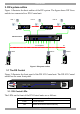
3. DX system outline
Figure 1 illustrates the basic outline of the DX system. The figure shows DX Users
and devices connected to a DX Central unit.
DX 832 Central
X-RICC
X-RICC X-RICC
132
Computer
To computers
Computer
MINICOM
Power
DX
User
User 4
User 1
MINICOM
Power
DX
User
User 8
MINICOM
Power
DX
User
DX UserDX UserDX User
Computer
PowerLink
MINICOM
DX432
Central
Figure 1 DX system outline
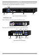
3.1 The DX Central
Figure 2 illustrates the front panel of the DX 832 Central unit. The DX 432 Central
model has the same front panel.
PowerLink
MINICOM
DX 832
Central
Figure 2 DX 832 Central front panel
3.1.1 DX Central LEDs
The LEDs on the front of the DX Central units are as follows:
LED Function
Power Power indicator
Link Blinks when there’s Ethernet activity