
User guide

DX SYSTEM
19
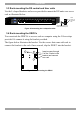
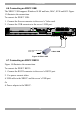
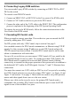
7.1 Connecting with an Ethernet Crossover cable
To connect a secondary level DX Central with an Ethernet Crossover cable:
Connect the Ethernet Crossover cable connectors to the Ethernet ports of the 2 DX
Centrals units, as illustrated in Figure 16.
POWER
www.min icom.com
ETHERNET
SERIAL
SERVICEI
0
1234
18192017
SERVER
5678
22232421
1234
6785
9101112
26272825
13141516
30313229
USER
POWER
www.minicom .com
ETHERNET
SERIAL
SERVICE
I
0
1234
18192017
SERVER
5678
22232421
1234
6785
9101112
26272825
13141516
30313229
USER
DX Central
- 1
st
level
DX Central
- Secondary level
Cascade
To User
ports
To Server
ports
Ethernet
Crossover
cable
CAT5 cables
1 for each DX User in
the system
Up to 8 for 8 x 32
Up to 4 for 4 x 32
To
Ethernet
ports
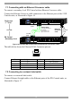
Figure 16 Cascaded DX Central units connected with a Crossover cable
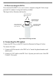
The table below shows the Ethernet RJ 45 Connector pin-out.
1
8
Pin Assignment Pin Assignment
1 TX + 5 Not connected
2 TX - 6 RX -
3 RX + 7 Not connected
4 Not connected 8 Not connected
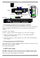
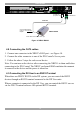
7.2 Connecting to a network hub/switch
To connect to a network hub/switch:
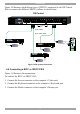
Connect Ethernet Straight cables to the Ethernet ports of the DX Centrals units, as
illustrated in Figure 17.