
User guide

DX SYSTEM
9
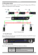
The figure below illustrates the rear panel of the DX 832 Central unit. The DX 432
Central model is the same but with only 4 User ports.
Power
connector
RS232 Service
port
User ports
POWER
100-250 VAC 50/60 Hz
www.minicom.com
Reset
button
Ethernet
ETHERNET
SERIAL
SERVICEI
0
1234
18192017
SERVER
5678
22232421
1234
6785
9101112
26272825
13141516
30313229
Server ports
RS232 Serial
port
USER
Figure 3 DX 832 Central unit rear panel
3.2 DX User units
Figure 4 illustrates the front panel of the DX User unit.
MINICOM
Power
DX
User
Figure 4 DX User front panel
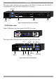
The figure below illustrates the rear panel of the DX User unit.
SYSTEM
Power
connector
POWER
100-250 VAC 50/60 Hz
www.minicom.com
I
0
Keyboard
Mouse
Monitor
Computer
Keyboard port
Computer
Mouse port
Computer
Video card
USB
LOCAL COMPUTER
TERMINAL
CONSOLECOMPUTER
USB
ports
RS232
Terminal port
RS232 port to
Local computer
Figure 5 DX User rear panel ports