DX System User Guide w w w . m i n i c o m . c o m International HQ North American HQ European HQ Jerusalem, Israel Linden, NJ, USA Dübendorf, Switzerland Tel: + 972 2 535 9666 minicom@minicom.com Tel: + 1 908 486 2100 info.usa@minicom.com Tel: + 41 44 823 8000 info.europe@minicom.com Technical support - support@minicom.com 5UM20121 V2.
DX SYSTEM Table of Contents Welcome................................................................................................................ 2 1. Introduction ....................................................................................................... 2 1.1 Features ....................................................................................................... 2 1.2 System components ...................................................................................... 2 1.
USER GUIDE 11.1.1 General information about Auto detect.......................................................................... 2 11.2 Applying changes ........................................................................................ 2 11.2.1 Configuring individual input ports................................................................................... 2 11.3 Cascaded DX Central units.......................................................................... 2 11.4 Cascaded Legacy switches..
DX SYSTEM 18. Connecting to a local computer ...................................................................... 2 19. Updating the DX Central.................................................................................. 2 19.1 System requirements for the DX Central Update program ............................. 2 19.2 Running the DX Central Update ................................................................... 2 19.2.1 Upgrading from V1.9 to V2.0 ..................................................
USER GUIDE Welcome Thank you for buying the DX system. This system is produced by Minicom Advanced Systems Limited. This document provides installation and operation instructions for Minicom’s DX system. It is intended for system administrators and network managers, and assumes that readers have a general understanding of networks, hardware and software.
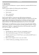
DX SYSTEM 1. Introduction The DX system from Minicom is a superior solution for centralized KVM & Serial management. The DX system combines the following four major functions: · KVM switching and control · Serial control · Power management · User management The DX unifies the above functions using AIM (Advanced Integrated Management). AIM is an innovative embedded Graphical User Interface (GUI) that supplies advanced management functionality in a hardware-only based solution.
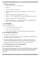
USER GUIDE 1.2 System components · DX Switch 432 (4 users) or 832 (8 users) · DX Users · DX User IP (has it’s own Guide) · X Remote Interface Connection cables (XRICCs) – PS/2, SUN, USB, RS232 · Remote Interface Connection cables (RICC) – PS/2 · Cables - 3 in 1 CPU cable, RS232 Serial cable, Ethernet Crossover cable · Rack mounts for the DX units and the XRICCs · Minicom Flash USB key – containing Installation and Operating guides and Central unit firmware Update program 1.
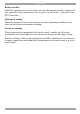
DX SYSTEM Reduced airflow Install the equipment in a rack in such a way that the amount of airflow required for safe operation is not compromised. Leave a gap of at least 5cm/2” each side of the DX Central unit. Mechanical loading Mount the equipment in the rack in such a way that a hazardous condition is not achieved due to uneven mechanical loading.
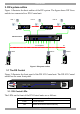
USER GUIDE 3. DX system outline Figure 1 illustrates the basic outline of the DX system. The figure shows DX Users and devices connected to a DX Central unit. User 4 User 1 MINICOM User 8 DX Pow er MINICOM User DX User DX 832 Central DX Pow er MINICOM User DX Powe r DX User MINICOM DX User DX 432 Power Link Central To computers 1 User X-RICC 32 X-RICC Computer Computer Computer X-RICC Figure 1 DX system outline 3.
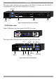
DX SYSTEM The figure below illustrates the rear panel of the DX 832 Central unit. The DX 432 Central model is the same but with only 4 User ports. RS232 Service port www.m inicom.
USER GUIDE 3.3 Rack mounting the DX central and User units Use the L-shaped brackets and screws provided to mount the DX units on a server rack as illustrated below. www.minicom.
DX SYSTEM 3.5 Rack mounting the RICCs You can attach the RICCs to a server rack or computer using the Velcro strips provided. Or connect it using the bracket provided. The figure below illustrates the bracket. Insert screws through bracket and into the rack Insert screw through bracket and into the back of a computer Insert screws through bracket and into the back of the RICC Insert screws through bracket and into the back of the RICC Figure 8 Rack mounting the RICC 4.
USER GUIDE P110 SD Optional local computer COMPUTER Mo use TERMINAL 100T CONSOLE Serial A SYSTEM USB LOCAL COMPUTER V ideo POWER 100-250 VAC 50/60 Hz Paral lel www.m inicom.com DX User KB I 0 S erial B CAT5 cable Up to 100M / 330ft 3 in 1 CPU cable DX Central www.minicom.
DX SYSTEM Figure 10 illustrates the different types of XRICCs connected to the DX Central. How to connect the different XRICCs follows in detail below. DX Central www.minicom.
USER GUIDE To Keyboard port Mouse Keybd Parallel Serial A RICC / XRICC PS/2 100T To Mouse port Video Serial B CAT5 cable to DX Central Server port To Video card Figure 11 RICC / XRICC PS/2 4.5 Connecting an XRICC SUN Figure 12 illustrates the connections. To connect the XRICC SUN: 1. Connect the Screen connector to the server’s Video card. 2. Connect the Keyboard connector to the server’s Keyboard port.
DX SYSTEM 4.6 Connecting an XRICC USB The XRICC USB supports Windows 98 SE and later, MAC, SUN and SGI. Figure 13 illustrates the connections. To connect the XRICC USB: 1. Connect the Screen connector to the server’s Video card. 2. Connect the USB connector to the server’s USB port. To Video Card CAT5 cable to DX Central Server port X-RICC USB Figure 13 XRICC USB 4.7 Connecting an XRICC RS232 Figure 14 illustrates the connections. To connect the XRICC RS232: 1.
USER GUIDE To USB Port (for power only) To RS232 Port USB cable Connect USB cable for power or connect Power adapter X-RICC RS232 CAT5 cable to DX Central Server port Figure 14 XRICC RS232 4.8 Connecting the CAT5 cables 1. Connect one connector to the XRICCs RJ45 port – see Figure 10. 2. Connect the other connector to one of the DX Central’s Server ports. 3. Follow the above 2 steps for each server/device.
DX SYSTEM 4.9.1 Connecting the RS232 terminal Connect the RS232 terminal to the DX User as illustrated in the figures below. Terminal Login: admin Password_| d i g i t a l VT420 Contr ast Bright To Terminal port www.minicom.com I 0 POWER 100-250 VAC 50/60 Hz CONSOLE COMPUTER TO CENTRAL TERMINAL USB LOCAL COMPUTER Figure 15 Connecting the RS232 terminal The table below shows the RS232 Serial cable 9 PIN D-SUB Male pin-out.
USER GUIDE 6. Connecting Legacy KVM switches You can cascade Legacy KVM switches by connecting an XRICC PS/2 or RICC PS/2 to the switch. To cascade a non-DX KVM switch: 1. Connect an XRICC PS/2 or RICC PS/2 to the User ports of the KVM switch. 2. Connect a CAT5 cable to the Server port of the DX Central. 3. Connect the other end of the CAT5 cable to the XRICC PS/2. The configuration process is explained at the beginning of the DX System Operating Guide.
DX SYSTEM 7.1 Connecting with an Ethernet Crossover cable To connect a secondary level DX Central with an Ethernet Crossover cable: Connect the Ethernet Crossover cable connectors to the Ethernet ports of the 2 DX Centrals units, as illustrated in Figure 16. www .minicom.
USER GUIDE www.minicom.
DX SYSTEM Figure 19 DX Network Configuration Here you configure the DX Central’s network settings. All DX Centrals come with the following predefined settings: · IP Address: 192.168.0.245 · Subnet Mask: 255.255.255.0 3. If the above predefined settings are not suitable for your network, type suitable parameters into the DX Network Configuration box. 4. Click . The Define DX status box appears. See Figure 20. Figure 20 Define DX status box 5. Select Primary unit and click 6. Click . .
USER GUIDE 9. The DX Central slave must have a different IP address than the primary DX Central, but it must be on the same subnet. Type suitable network parameters for the DX Central slave into the DX Network Configuration box. 10. Click . The Define DX status box appears. See Figure 20. 11. Select Slave and click . The following box appears. Figure 21 Primary DX unit IP address box 12. Type in the IP address of the primary DX Central unit. 13. Click . The Login screen appears. 14.
DX SYSTEM 7.6 Connecting servers/devices in a cascaded system You can connect servers/devices to any available Server port on any level DX Central. 8. Powering on the system The devices and servers can be powered on at any time. Power on the DX components in the following order: 1. The primary and secondary level DX Centrals. 2. The DX Users. 9. Configuration wizard (non-DX cascaded system) For cascaded DX systems, skip to section 10.
USER GUIDE 10. Logging in Once the system is connected and powered on, the Login screen appears on the monitor of each DX User. See Figure 23. Figure 23 Login screen Type the default username ‘admin’ and password ‘admin’ (case sensitive). The Servers window appears. See Figure 24. The screen initially shows no devices. To display the devices the system must be configured, as explained below. Toolbar icons Created folders appear here Servers / devices appear here Figure 24 Servers window 11.
DX SYSTEM Input ports to DX User units Output ports to devices List of DX Central units and other KVM switches Information about currently selected switch Figure 25 DX System Configuration window The above figure shows the rear ports of a DX Central unit. You can view the rear ports of all DX Central units and Legacy switches connected to the system by clicking a switch from the list on the left. After configuring the system, the ports appear color coded as outlined by the list of RICC Types.
USER GUIDE 11.1.1 General information about Auto detect Each device auto-detected receives a default name e.g. 1Server01. All devices have the default timeout period of 60 seconds. When a server is accessed, after 60 seconds of inaction another user may take control of the server or the present user can regain control by moving the mouse or typing on the keyboard. You can change this timeout period. All devices have the default keyboard mode set to PS/2 for Intel based computers.
DX SYSTEM Figure 27 RS232 Terminal settings Timeout – Type a timeout period or check the Infinitive box to disable the timeout feature. KB Mode – Select the appropriate keyboard mode. By default the keyboard mode is set to PS/2 for Intel based computers. For other systems set the KB mode as follows: · U1 for HP UX · U2 for Alpha UNIX, SGI, Open VMS · U3 for IBM AIX 11.2 Applying changes In general, to apply changes you may have the following 3 options.
USER GUIDE 11.2.1 Configuring individual input ports Configure the input ports to display the DX User icon. To configure the input ports: 1. On the picture of the switch in the DX System Configuration window, click an input port . The Configuration box appears see Figure 28. Figure 28 Configuration box 2. Input Type - From the menu select User Unit. The Configuration box now appears as in Figure 29. Figure 29 Configuration box 3.
DX SYSTEM 4.Terminal Type – For RS232 devices in the DX system, the DX User can control them via a terminal emulation window. To operate the RS232 devices with the DX built-in terminal software – select Internal. Where a Serial cable connects a computer to the DX User and the emulation software is installed in the computer, or when using an external Terminal – select External. 5. The Cascade box is explained in the section below. 6.Managed by KVM.
USER GUIDE Figure 31 Cascade tab 4. General – From the drop-down menu select the lower level DX Central. 5. Input port No: – From the drop-down menu select the lower level User port the upper level Server port is connected to. For example in Figure 30 Server port 1 is connected to User port 1. 6. Click OK. Do the above for each cascaded Server port. After step 1 above, you can achieve the same result by doing the following: From the toolbar click . The DX Central Properties box appears.
DX SYSTEM Name – From the drop-down menu select the lower level DX Central. (Right) Port No: - From the drop-down menu select the lower level User port the upper level Server port is connected to. Do the above for each cascaded Server port. Click Save. Method B - lower level DX Central 1. From the list of DX switches, click the lower level DX Central. A figure of its ports appears. Note! An alternative method to steps 2-6 is set out in the bordered wording below. 2.
USER GUIDE Figure 34 Cascade Inputs (Left) Port No: - This refers to the User port numbers. Name – From the drop-down menu select the higher level DX Central this User port cascades to. (Right) Port No: - From the drop-down menu select the higher level Server port the lower level User port is connected to. Do the above for each cascaded User port. Click Save. Do the above for each cascaded port. Click OK. 11.
DX SYSTEM 11.4.1 Adding a Legacy switch To add a new Legacy switch: Click . The Add New KVM Device box appears. See Figure 35. Figure 35 Add New KVM Device box The General tab elements Name – Type an identifying name for the new Legacy switch. Type – From the Drop-down list select the new device type. If it doesn’t appear in the list, it can be added (explained below - Adding a Legacy switch type). Users / Servers – Displays the maximum number of users and servers for the device selected.
USER GUIDE Figure 36 Add New Device Type box 2. Type a name for the Legacy switch type (This is not the same as the Name field in Figure 35. This is name of the switch type that will appear in the Type dropdown menu in Figure 35). 3. Select the number of input and output ports in the Legacy switch. Figure 37 below illustrates input and output ports. The input ports connect to a RICC or XRICC and the output ports connect to the servers. www .minicom .
DX SYSTEM 11.4.2 Editing a Legacy switch type To change the number of input and output ports for a Legacy switch type: 1. Click Figure 38. . The currently selected device Properties box opens. See Figure 38 Properties box 2. Change the number of input/output ports (see Figure 37), check or uncheck Typematic as necessary and click . Note! From the DX System Configuration window you can edit a Legacy switch type by selecting it from the list of switches and from the Toolbar pressing . 11.4.
USER GUIDE Figure 39 Cascade Inputs box Left Port No. A row appears for each input port of the Legacy switch. Name – From the Drop-down list select the DX Central to which the switch is cascaded 1 level up. Right Port No – Select the Server port number of the 1 level up DX Central to which the switch is connected. Do the above for each cascaded port. Click OK. Note! You can configure the cascade inputs by clicking the User ports on the figure of the Legacy switch. See Figure 41. Method B 1.
DX SYSTEM Figure 40 Cascade box General – Select the cascaded Legacy switch from the Drop-down list. Input Port No – Select the input port number of the Legacy switch that connects to the DX Central. Save changes. 11.4.4 Configuring the server ports Configure the server ports of cascaded Legacy switches. You must give each server an identifying name and select the appropriate XRICC type and keyboard mode. You must also type the appropriate KVM switch access hotkey to the server.
USER GUIDE 2. Click a Server port. The Computer port configuration box appears, see Figure 42. Figure 42 Computer port configuration box Name – Type a name for the connected device, it appears below the device in the Servers window. Type – Select Generic KVM port. Timeout – You can change the timeout period or check the Infinitive box to disable the timeout feature. KB Mode – Select the appropriate keyboard mode. By default the keyboard mode is set to PS/2 for Intel based computers.
DX SYSTEM 2. Press the hotkey keys on your physical keyboard or on the soft keyboard. The keys appear in the HotKey box. Some KVM switches may require a pause or two between the hotkey keys. Use the Insert Pause button to add pauses. 3. Click Assign. The hotkey is assigned. Note! For hotkeys that require a key to be continually pressed see the Typematic paragraph on page 2. 11.4.5 Deleting a Legacy switch To delete a Legacy switch: Select the desired switch from the list in the DX Configuration window.
USER GUIDE 11.5.1 Adding a new Power profile To add new Power profile: Click . The Add New Power Profile box appears, see Figure 45. The information you need to type should be in the Power device instructions. Figure 45 Add New Power Profile box The Add New Power profile box elements Power Profile Name - Give the profile a name. Sockets No – Type the number of power sockets in the device. Session Start/End. Power On/Off. Reboot – For this information see the power device instructions.
DX SYSTEM 11.5.2 Configuring the connected servers You need to configure the Computer ports to show the connection to the Power device. To configure the Computer ports: 1. Click a Computer port (connected to the Power device) on the picture of the switch. The Computer Port Configuration box appears. 2. Click the Power tab, the following appears. Figure 46 Power tab Power Device – Select the Power device from the drop-down menu. Drop-down menus for the Power switch No and Socket No appear.
USER GUIDE Figure 47 Dual Power devices 3. Save changes. 11.6 Other settings to configure From the Tools menu click Settings, the Settings window appears. See Figure 48. Important! Some of the elements in this window must be configured BEFORE using the DX system. Failure to do so will make the system inoperative. Each section of the window is explained below.
DX SYSTEM 11.6.1 Admin (User name) Settings (The title of this section reflects the current user’s name.) Name – Name given to the DX Central the DX User connects to. In a cascaded configuration this would be the name of the primary DX Central. MAC – MAC address of the above DX Central. Keyboard Layout- Select your keyboard layout, English, French or German. Language - Select your language - English, French German or Italian. When saved the menus and other text appear in the chosen language.
USER GUIDE From the File menu choose Log off. The Login screen appears and the Administrator can enter his password. Security On – When checked Users must login to access the AIM. Security High – When checked Users must login every time they connect to a server/device. Relate name – You can relate the name of each device to either the Server or Port. When related to the Server, the device can be connected to any DX Central Server port, without the need to reconfigure the port.
DX SYSTEM 11.6.4 Extensions Enable Screen Saver – Check to enable the DX screen saver. The screen saver appears if there is no activity for 5 minutes after the Timeout login screen appears. This 5 minute time period cannot be altered. Enable Direct Connection - Check to enable Users to use a hotkey to directly connect to a device without having to access the AIM. See Direct Hotkey on page 2 above.
USER GUIDE Group members Groups Figure 49 Users and Groups window By default there are 3 Groups in the Groups column. Each Group has specific access rights that cannot be altered. The 3 default Groups are: Group Administrators Access rights Full access and power management of all computers.
DX SYSTEM 12.1 Toolbar buttons You create and edit Users and Groups using the Toolbar buttons. The table below explains the functions of the Toolbar buttons. Button Function Add User Add Group Delete Properties Save 12.2 Creating Groups An Administrator can create Groups and give them tailor-made access permissions. To create a Group: Press . The Add New Group box appears. See Figure 50.
USER GUIDE 12.2.1 General information tab elements Group name – Edit the Group name here. Description – type a description of the group. Timeout –After this period of inaction a Group member is forced out of the system and must re-login. You can type a different Timeout period. Private connection – When a Group member accesses a computer, Private connection gives the option to prevent other users from viewing the computer. Can change password – check to allow members to change their passwords. 12.2.
DX SYSTEM 12.2.3 Defining the same access rights for all devices To give the Group the same access right to every device, click the desired option button at the top of the column. E.g. to give the Group, viewing access to every device: Click and confirm. 12.3 Editing Group access rights An Administrator can change General information and Access Rights of nondefault Groups in the following way: 1. Double-click the Group icon or select the Group icon and click Properties box appears. See the figure below.
USER GUIDE Figure 53 Add New User box User Name – Type a name for the User (case sensitive). This name appears below the User’s icon in the Users and Groups window. Full Name - Type the User’s full name. Description – Type a description of the User. Password/Confirm password – Type a login password and confirm it (case sensitive). This can be left blank, so no password is required at login, just the Username.
DX SYSTEM 12.4.1 Editing the User box An Administrator can edit all the elements that appear in the User box, including the password and he can move the User to a different Group. To display a User box: 1. Double-click the User icon or select the User icon and click . 2. Edit and click OK. 3. Save changes. 12.5 Users and Groups - Details view You can view the Users and Groups window from the servers’ point of view. To do so: 1. Select View/Details. The Details view appears see Figure 54. 2.
USER GUIDE 13.1 The Servers window From the View menu select Servers/Devices, the Servers window appears. See Figure 55. Figure 55 Servers window 13.1.1 Device Icon appearance The table below explains the color-coding of the icons in the Servers window.
DX SYSTEM The Toolbar buttons and their functions are explained in the following table. Button Function Connect to server/devices Connect to local PC Power on (Blue) Power off (Red) Reboot (Green) Search for folder/device by name Sort devices alphabetically A-Z Sort devices alphabetically Z-A 1 level up Create new folder Cut device to paste to another folder Paste Delete folder Save 13.2 Creating a new folder To create a folder: From the Edit menu, choose Add Folder Or. Click . A new folder appears.
USER GUIDE 13.3 Saving changes To save any changes made in any window: From the File menu click Save changes. Or Click . 13.4 Deleting and renaming folders To delete a folder: 1. Highlight the desired folder. 2. From the Edit menu choose Delete Folder or press Delete. The folder deletes. To rename a folder: 1. Highlight the desired folder. 2. From the Edit menu choose Rename Folder. 3. Give the folder a new name. 13.
DX SYSTEM From the View menu choose Icons, List or Details. Figure 56 shows the Details view. In List view, view up to 100 devices without the need for scrolling. In Detailed view, you see the device name, Direct hotkey (discussed on page 2), port number, XRICC type etc. Figure 56 Details view 13.7 Accessing devices To access a device: From the Servers window double-click a device. Or select the device and click Or select the device and choose Action/Connect. Or press the hotkey.
USER GUIDE 13.8 Power on/off, reboot The power options are available to Administrators and to Users with Power management rights. To perform these power functions: 1. Select the desired device. 2. Select the desired function from the Toolbar buttons or the Action menu. 14. Scanning a group of servers You can set up a group of servers, and scan their monitors at a speed that you choose. To set up a scan group: 1. From the Action menu choose Scan. The Scan box appears see Figure 57. Figure 57 Scan box 2.
DX SYSTEM 4. From the list of servers on the left, highlight the desired servers/devices and press . To add all servers (without highlighting), press . The servers transfer to the right and are included in the scan group. To remove servers from the scan group: Highlight the desired server and press . To remove all servers (without highlighting), press 5. Use the in the scan group. and . arrows to change the order of the servers 6. Click OK. The Scan box reappears. 7. Set the scan time.
USER GUIDE 16. Connect - Private This option appears in the Action menu and is available to Administrators and to Users with private connection rights. See page 2. To activate Connect - Private: 1. Select the desired device. 2. From the Action menu select Connect - Private. Other Users are prevented from viewing the selected computer. 17. Disconnect User An Administrator can disconnect a user from any device. To disconnect a user: 1. Select the desired server/device. 2.
DX SYSTEM 19.2 Running the DX Central Update Install the program on any Windows-based computer connected to the DX network. A shortcut icon appears on the Desktop · DX Central Update · Upgrading from V1.9 to V2 . There are 2 Update options: Where you have V1.9 installed you must first upgrade from V1.9 to V2. Once V2 is installed you use the DX Central Update program. The Desktop icon only opens the DX Central Update. 19.2.1 Upgrading from V1.9 to V2.0 1.
USER GUIDE Figure 61 Update Options screen 4. Check Update DX and click Next. 5. Locate the V2 upgrade file and click Open. The firmware upgrades. Once the DX Central firmware is upgraded to V2, all future updates are done using the DX Central Update program. 19.2.2 DX Central Update All updates for DX Central with V2 firmware are done through DX Central Update. 1. Select Start/Programs/DX Central Update/ DX Central Update or click the Desktop icon. The Welcome to DXC update utility box appears.
DX SYSTEM Figure 64 DXC update utility options You can choose any of the following: · Check version · DX Central Settings (Check and/or change the settings) · Update the DX Central firmware · Restore factory defaults – and erase the current database · Backup System (database) · Restore System (by loading a saved database) To do any of the above, check the desired option and click Next. 4. Under DX Central Settings, you can change the DX Central network settings or IP address.
USER GUIDE Warning! Never switch off any User unit or computer connected to the system during the updating process. 1. Download the latest firmware to your hard disk and unzip it to the Minicom Flash USB key. 2. From the DX GUI, select Tools/Update. The Update window appears see Figure 65. Figure 65 Update window 3. Insert the USB key into a USB port of a DX User. 4. Click the picture of the device type to be updated. When selecting the DX User, it’s version details appear in the middle section.
DX SYSTEM Figure 66 Open File box 6. Select the firmware file and click Open. The file appears in the information section of the Update window. 7. Select . The firmware updates. 8. Reboot the DX User unit. 20.1 DDC buttons All XRICCs come with the default DDC information of: 1024x768@75Hz. Where the monitor connected to the DX User has a different resolution, select all . XRICCs/RICCs and press If you need to return the XRICCs to the default DDC information, select all the .
USER GUIDE Figure 67 Log window 21.1 Configuring Log Traps By default event logging is disabled. An Administrator can configure which log traps to send to the SNMP Manager as follows: 1. Click . The Log Settings window appears see Figure 68. Figure 68 Log Settings 2. Scroll down the list. Check those you wish to be sent. To check or uncheck all events click the events category button at the top of the column.
DX SYSTEM 3. You can choose the icon that appears in the Type column in the Log window to an event - Figure 67. There are 3 icon options – info, error and warning. To change an individual event icon, check the appropriate column in the Log Settings window. To have all events with the same icon, press the appropriate button at the top of the column. Note: You can always return to the default status by pressing the Default button.
USER GUIDE 23. USB / SUN Combo keys The connected PS/2 keyboard does not have a special SUN keypad to perform special functions in the SUN Operating System environment. So when a XRICC USB or SUN is connected to a SUN computer, the XRICC emulates these SUN keys using a set of key combinations called Combo keys. See the table below.
DX SYSTEM 24. Technical specifications System Operating systems Resolution Novell, LINUX, Windows, UNIX SUN, MAC and other major operating systems 1600 X1200 @75Hz User to server distance 200m/660ft System cable CAT5, CAT6, CAT7 Operating temp. Storage temp.
USER GUIDE RICCS RICC PS/2 for DX Server to DX Central Distance XRICC PS/2 XRICC SUN 10m/33ft XRICC USB XRICC RS232 100m/330ft Cables/Connectors System - RJ45 Video – HDD15 K/M – MiniDin8 K/M - MiniDin6 Rack mountable Power supply Dimensions Serial DB9 K/M - USB Power Jack From USB Power Adapter or from USB Yes From Keyboard 24x91x41mm / 0.94x3.58x1.61” 26x91x45mm / 1.05x3.58x1.77” 25.
DX SYSTEM 26. Safety The device must only be opened by an authorized Minicom technician. Disconnect device from AC mains before service operation! The DX Central units contain a lithium battery. Caution. Risk of explosion if battery is replaced by an incorrect type. Dispose of used batteries according to the instructions. 27. User guide feedback Your feedback is very important to help us improve our documentation. Please email any comments to: ug.comments@minicom.
USER GUIDE Regional Offices Germany France Italy Kiel Vincennes Rome Tel: + 49 431 668 7933 info.germany@minicom.com Tel: + 33 1 49 57 00 00 info.france@minicom.com Tel: + 39 06 8209 7902 info.italy@minicom.com England Camberley Tel: + 44 (0) 1276 25053 info.uk@minicom.com www.minicom.
DX SYSTEM 71