CAT5 AV Splitter User Guide Audio & Video Splitter 5UM40066 - V1 8/01
Table of Contents Introduction 1 The CAT5 AV Splitter 1 Features 2 Overview 3 Installing the AV Splitter system 5 Connecting the Central unit 5 Connecting the remote units 8 Operating the AV Splitter system 10 Adjusting the screen picture 10 The Long Range Remote unit – Adjusting the brightness 10 Adjusting the volume 11 Technical Specifications 12
Introduction Minicom Advanced Systems Ltd (Minicom) is a leading manufacturer of KVM switches for multiple server control. Minicom also manufactures interactive systems for Computer Equipped Learning Environments. It is also the world leader in the development and deployment of cutting edge CAT5 technology. The CAT5 AV Splitter The CAT5 AV Splitter (AV Splitter) system from Minicom simultaneously broadcasts audio and video signals to 2 or 4 Remote monitors and speakers up to 250m / 820ft away.
Features • Pure hardware Plug and Play • Two Remote models to choose from • Compatible with all major brands of Sound cards • Cascadable • Supports high resolution monitors (1280x1024) • Transmits audio and video signals along CAT5 cable • Individual picture adjustment 2
Overview The AV Splitter system consists of: A Central unit – either a 2 or 4 port model Plus the following: • VGA cable • Stereo Plug cable • Power adapter - either 110V or 220V • Power cord Remote or Remote Long Range units Plus the following: • Power adapter - either 110V or 220V • Power cord Use CAT5 cables to connect the remote units to the Central unit. Figure 1 illustrates the AV Splitter system configuration for the 4-port Central unit.
Monitor Speakers Remote unit ON 9 VAC OFF PICTURE MONITOR TO CENTRAL UNIT AUDIO OUT Monitor Speakers Remote unit ON 9 VAC OFF PICTURE MONITOR TO CENTRAL UNIT AUDIO OUT Monitor Speakers TO REMOTE UNIT ON Central unit 9 VAC OFF LOCAL MONITOR VIDEO IN 1 2 3 AUDIO 4 IN OUT Computer Mouse Computer Monitor Speakers Remote unit 9 VAC OFF Keyboard Remote unit ON PICTURE MONITOR TO CENTRAL UNIT AUDIO OUT Monitor Speakers Remote unit CAT5 FTP cables ON 9 VAC OFF PIC
I n s t a l l i n g t h e AV S p l i t t e r s ys t e m Before installing the system do the following: • Place cables away from fluorescent lights, air conditioners, and machines that are likely to generate electrical noise. • Ensure that the distance from the Central unit to each Remote unit does not exceed the maximum cable length. Connecting the Central unit Figure 2 illustrates the ports and functions of the 4-port Central unit back panel.
Connect the following to both models of the Central unit back panel: • Monitor’s cable • VGA cable • CAT5 cables • Speakers (optional) • Stereo Plug cable • Power adapter Figure 3 below illustrates the back panel connections of the 4-port model.
RJ-45M to Remote units 1-4 Monitor Speakers CAT5 cables HDD15M to Local Monitor port Aux Out plug to Audio Out port RJ-45M to ports 1-4 TO REMOTE UNIT ON 9 VAC OFF DIN4M to Power port LOCAL MONITOR VIDEO IN 1 2 3 HDD15F to Video In port AUDIO 4 IN AV Splitter Central unit OUT Aux In plug to Audio In port VGA cable D To wall socket Power cord Stereo Plug cable MiniDIN6M to computer's Keyboard port Power adapter MiniDIN6M to computer's Mouse port HDD15M to computer's Screen port
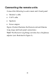
Connecting the remote units Connect the following to each remote unit’s back panel: • Monitor’s cable • CAT5 cable • Speakers • Power adapter Figure 4 below illustrates the Remote unit and Remote Long range unit back panel connections. Note! The Remote Long Range unit also has a brightness adjuster (not illustrated in figure 4).
RJ-45M to Central unit Monitor CAT5 cable HDD15M to Monitor port RJ-45M to CAT5 cable port AV Splitter Remote unit ON 9 VAC OFF DIN4M to Power port D To wall socket Power cord PICTURE MONITOR TO CENTRAL UNIT Aux Out plug to Audio Out port AUDIO OUT Speakers Power adapter Figure 4 The Remote unit back panel connections 9
O p e r a t i n g t h e AV S p l i t t e r s ys t e m To prepare the system for operation: 1. Connect the AV Splitter system. 2. Switch on the computer. 3. Switch on the AV Splitter units. The computer screen image and audio sound will be broadcast to all the remote units. Adjusting the screen picture When the picture on a remote screen needs adjusting, use a screwdriver to turn the Picture Adjuster on the remote unit.
Adjusting the volume Use the Windows volume control to adjust the volume of all Remote units simultaneously. Or adjust the individual speakers at each remote unit.
Te c h n i c a l S p e c i f i c a t i o n s Resolution Dimensions Weight Power supply Up to 1280 x 1024 - 75 Hz Central unit 30mm x 78mm x 224mm Remote unit 30mm x 78mm x 157mm Remote Long Range unit 30mm x 110mm x 190mm Central unit - 450g Remote unit - 260g Remote Long Range unit 575g External 110V or 220V 2 x 9VAC 2A Operating temperature Up to 500C Storage temperature - 400C to 700C Screens VGA, SVGA, XGA 12
Video Interface Video Signal: Analog Signal Red Green Blue 0.7Vp-p/75 Ω positive Sync: TTL Compatible Horizontal: Sync. positive/negative Vertical: Sync.
Headquarters USA German Europe Minicom Advanced Systems Ltd. Minicom Advanced Systems Inc. Minicom Advanced Systems Minicom Advanced GmbH Systems Srl. Jerusalem Israel Tel: +972 2 651 8593 Fax: +972 2 651 8971 New Jersey, USA Tel: toll free: +1 888 486 2154 Tel: +1 908 486 2100 Fax: +1 908 486 7788 Zurich, Switzerland Tel: +41 1 455 6220 Fax: +41 1 455 6225 Web site - www.minicom.com Italy Rome, Italy Tel: +39 06 8209 7902 Fax: +39 06 8209 7903 www.minicom.it Customer service - minicom@minicom.