DS Vision 3000 User Guide w w w . m i n i c o m . c o m International HQ North American HQ European HQ Jerusalem, Israel Linden, NJ, USA Dübendorf, Switzerland Tel: + 972 2 535 9666 minicom@minicom.com Tel: + 1 908 486 2100 info.usa@minicom.com Tel: + 41 44 823 8000 info.europe@minicom.com Technical support - support@minicom.com 5UM40169 V1.
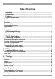
DS VISION 3000 Table of Contents 1. 2. 3. 4. Welcome ........................................................................................................3 Introduction ...................................................................................................4 Features .........................................................................................................4 System components......................................................................................
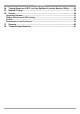
USER GUIDE 14. 15. 16. Tuning Receivers L/DCL (or Line Splitters/L) via the Service Utility.........29 Remote Tuning ............................................................................................33 Service .........................................................................................................36 Upgrading firmware..................................................................................................... 37 Display Data Channel (DDC) hotkey ........................
DS VISION 3000 1. Welcome Thank you for buying the DS Vision 3000 system. This system is produced by Minicom Advanced Systems Limited. This document provides installation and operation instructions for Minicom’s DS Vision 3000. Technical precautions This equipment generates radio frequency energy and if not installed in accordance with the manufacturer’s instructions, may cause radio frequency interference. This equipment complies with Part 15, Subpart J of the FCC rules for a Class A computing device.
USER GUIDE 2. Introduction The DS Vision 3000 (DS Vision) system from Minicom is an out-of-band solution for the last step in a digital signage network. DS Vision combines video, stereo/audio and serial functions for distributing real-time multimedia content from player to multiple screens up to 600m/2,000ft away. The DS Vision system distributes Video, Audio and Serial control data from a single content source to up to thousands of remote monitors over CAT 5/5e/6/7 Twisted Pair media.
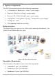
DS VISION 3000 4. System components The DS Vision system consists of the following components: · A Transmitter or Broadcaster + cables + power supply · Receivers / Receivers L (Long) + power supply · Receivers DCL (Dual Cascade Long) + power supply · Line Splitters / Line Splitters L (Long) + Tuning cable+ power supply.
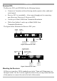
USER GUIDE The figure below illustrates the Broadcaster 8 port model. The ports are the same for the Transmitter and Broadcaster 16 port model, except for the number of System ports. The Transmitter has 1 System port and the Broadcaster 16 port model has 16 System ports.
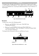
DS VISION 3000 System cable 5VDC Tuning adjuster SYSTEM TUNING Power connector Figure 4 Receiver – side 2 Serial Download cable System cable 5VDC SYSTEM TUNING Power connector Figure 5 Receiver L – side 2 7
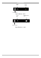
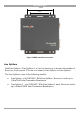
USER GUIDE Receiver DCL The Receiver DCL p/n 0VS50006 has the following features: · Connects to 2 monitors with each having totally separate video, audio and serial control · Receiver DCL is cascadeable – it has a pass-through port for connecting more Receivers/ Receivers L/ Receivers DCL · Can be up to 300m/1,000ft from Transmitter/Broadcaster · With a Line Splitter L can be up to 600m/2,000ft from Transmitter/Broadcaster The figures below illustrates the Receiver DCL ports System cable In SYSTEM
DS VISION 3000 100mm 75mm Figure 8 VESA standard screw holes Line Splitters Add Line Splitters / Line Splitters L to use for clusters or to increase the number of Receivers in the system. You can even connect Line Splitters to Line Splitters. The Line Splitters come in the following models: · Line Splitter - p/n 0VS50001. With Line Splitters, Receivers can be up to 110m/360ft from Transmitter/Broadcaster · Line Splitter L - p/n 0VS50002.
USER GUIDE The figure below illustrates the Line Splitter / Line Splitter L ports. Serial Download cable SY STEM OUT 5VDC TUNING SYSTEM IN Power System cable connector to Broadcaster System cables to Receivers Figure 9 Line Splitter LEDs The table below explains the functions of all the LEDs of the units in the system. Unit LED Function Transmitter / Broadcaster Front panel - Green Receiver / Receiver L RJ45 System port.
DS VISION 3000 Tuning Unit The optional Tuning Unit p/n 0VS50008 is used to manually tune Receivers L / Line Splitters or to download preset tuning parameters. The figure below illustrates the Tuning Unit. Figure 10 Tuning Unit 5. DS Vision applications The figures below illustrate the versatility of the DS Vision system. Figure 11 shows a basic installation with a Receiver and Receiver L. Receivers can be up to 110m/360ft away from the Transmitter/Broadcaster.
USER GUIDE Player 100m/330ft Receiver 300m/1,000ft 100m/330ft Line Splitter Long Transmitter/Broadcaster Receiver Figure 13 Long cluster Figure 14 and Figure 15 show different mixed installations with different combinations of Line Splitter and Line Splitter L and Receiver and Receiver L.
DS VISION 3000 Figure 18 shows a Line Splitter L cascaded to a Receiver DCL. Receiver DCL Player 300m/1,000ft 100m/330ft 200m/660ft Line Splitter Long Receiver DCL 300m/1,000ft Receiver DCL Transmitter/Broadcaster Figure 18 Receiver DCL + Line Splitter L Figure 19 shows two Receiver DCL units cascaded to 300m/1,000ft. (You can cascade up to 10 levels of Receiver DCL / Line Splitters).
USER GUIDE 7. The DS Vision cables The DS Vision cables are illustrated below. All these cables connect to the Broadcaster/Transmitter and player.
DS VISION 3000 8. Connecting the cables The connections illustrated in Figure 21 are described below. The detailed connection of the Receiver DCL is illustrated in Figure 22.
USER GUIDE 3.Connect the Stereo Audio cable to the Broadcaster/Transmitter Audio in port and the Computer’s Line Out port. 4.To use the Video Service Utility, connect the Serial Download cable to the Broadcaster/Transmitter Control port and the Computer’s Serial port. 5. (Optional) Connect a monitor to the Broadcaster/Transmitter Video Out port. 6.(Optional) Connect speakers to the Broadcaster/Transmitter Audio Out port. 7.(Optional) Connect a local Serial device to the Local port.
DS VISION 3000 System In CATx cable from Transmitter/Broadcaster or Line Splitter/L or Receiver DCL unit Screen 1 System Out CATx cable to Line Splitter/L or Receiver* unit Screen 2 Serial port / device Receiver DCL side 1 SYSTEM IN SYSTEM SERIAL 1 SYSTEM OUT 1 Video Speakers / Audio Receiver DCL side 2 TUNING SERIAL 2 Serial port / device TUNING5VDC 2 AUDIO VIDEO 1 VIDEO 2 Video Speakers / Audio * Receivers refers to any of the following: Receivers Receivers L Receivers DCL Figure 22
USER GUIDE 9. Adjusting the picture quality When the broadcasted picture needs adjusting: For the Receiver turn the Tuning adjuster – see Figure 4, using a small screwdriver. The Receiver L/Receiver DCL/Line Splitters can be tuned either via the Service Utility, as explained on page 29, or by using the optional Tuning Unit as explained below. Note! Where there are cascaded Receiver DCL/Line Splitters you must tune them from the unit nearest the Broadcaster/Transmitter onwards. See diagram below.
DS VISION 3000 Choose the preset distance closest to the actual distance in meters between the Player and remote screen. This will give you a fairly accurate tuning, which can be further finely tuned using the other functions of the Tuning Unit. To tune an image: 1.Scroll to Tables 2.Use the arrow keys to browse through all the predefined tables. 3.When you reach the desired table, press the Menu key. MNU=SAVE appears in the LCD and the table downloads. During downloading the LCD message blinks. 4.
USER GUIDE 11. Installing the Service utility The Service utility is located on the supplied CD and on our website www.minicom.com in the Support section.
DS VISION 3000 Figure 24 Control window Com port Choose Tools/Options. The Preferences window appears see Figure 25. In the Com port field select the Com port to which the Serial Download cable is connected to. Figure 25 Preferences window Language In the Preferences window above, you can change the language of the Service Utility GUI to be: Chinese, French German, Italian, Portuguese, Russian, Japanese or Ukrainian. To change the language: 1.
USER GUIDE 12. Topology To utilize the Service Utility functions you must configure the system topology. To configure the system topology, click the Topology tab* or select View/ Topology. (*For some operating systems the tabs on the Service Utility need to be doubleclicked). The following appears. Title line (Indicates if the Utility is online or offline) Figure 26 Topology tab You can detect the topology automatically or configure it manually.
DS VISION 3000 Figure 27 Auto-detected topology Note! You can detect the current topology at any time by pressing This fully updates all connected and disconnected ports. . Note! Auto-detect deletes all names given to particular ports. Naming ports is explained on page 25. Callouts Hold the mouse over any of the rows in the menu tree or over any button. A callout appears with information about the device or button function.
USER GUIDE Check When units have been connected or disconnected since last detecting the topology you can check for any changes to the topology. To do so: 1.Click undefined . Any new units detected appear as connected but . You must still define the unit. 2.To manually define the units connected to the ports, click the checkbox of a port or a number of ports that have the same device connected. 3.Click . A drop-down menu appears. 4.Select the device type.
DS VISION 3000 Figure 29 Manually displayed topology 3.To define the units connected to the ports, click the checkbox of a port or a number of ports that have the same device connected. 4.Click . A drop-down menu appears. 5.Select the device type. Note! When the device is a Line Splitter, repeat the process of defining the connected devices for each port of the Line Splitter. Naming a port To give a port an identifying name: 1.Check the port number (ensure that no other ports are checked).
USER GUIDE 1.Select the ports you want to include in the Group. 2.Click . The Enter name box appears. 3.Type a name for the group and click OK. The Group appears on the left. Groups appear here Figure 30 Saving a Group To see the selected ports of a Group, hold the mouse over the Group name or folder or check box, a callout appears showing the selected ports. Deleting a Group To delete a Group: Select the Group and click .
DS VISION 3000 13. Controlling the system To control the system: Click the Control tab or choose View/Control, the Control window appears, see Figure 31.
USER GUIDE From the icons on the right hand side: Click an icon to select it. To select more than one icon, hold down Shift or Ctrl and select the desired icons. Selecting all To select all: Choose Edit/Select All. Control of Receiver DCL monitors The two monitors connected to a Receiver DCL are controlled completely independently. Figure 32 shows the two monitors connected to a Receiver DCL. They are separate and clearly defined as [1] and [2].
DS VISION 3000 Sending/blocking video Click to toggle between sending and blocking video. When receiving video the device icons appear like this: . When not receiving video the device icons appear like this: . Sending/blocking Audio Click to toggle between sending and blocking audio. When receiving audio the device icons appear with a speaker like this: . Sending/blocking a Serial command Click to toggle between sending and blocking a Serial command.
USER GUIDE To tune from the Transmitter/Broadcaster position: Connect the Serial Download cable to the Control port of the Transmitter/Broadcaster and the Serial port of a computer which has the Service Utility installed. To tune from the Receiver L/DCL or Line Splitter/L position: Connect the Serial Download cable to the units Tuning port and the Serial port of a computer containing the Service Utility. See the figure below.
DS VISION 3000 Figure 34 Test card 2.Click the Tuning tab or select View/Tuning. The Tuning window appears see Figure 35 and Figure 36.
USER GUIDE Figure 36 Tuning window from Line Splitter L position 3.The Drop-down menu contains preset tuning configurations for distances of between 1m and 300m. Note! These presets were made using a test cable which may not be an exact match for the cable that you are using. Choose the preset distance that is closest to the actual distance in meters between the Player and remote screen. 4.For fine tuning use the sliding bars to adjust the image. The bars are as follows.
DS VISION 3000 Faster Red Green Blue Slower Figure 37 RGB signals 5.Once you have a satisfactory image, press Store to keep the present tuning configuration in the device memory. Restore – If after changing values you change your mind, you can restore the values to how they were the last time the Store button was pressed by pressing Restore. The current tuning parameters can be saved and used later for the same device, or another device connected with the same cable length and type. To do so: 1.
USER GUIDE http://192.168.111.132 Remote tuner at the screen LAN DS Vision Service Utility installed here Broadcaster Receivers Line Splitter Player - IP: 192.168.111.132 Figure 38 Remote tuning At the player the setup is done as follows: 1.Connect the Serial Download cable to the Broadcaster/Transmitter and player. 2.Open the Service Utility and choose Tools/Options, the Preferences window appears, see Figure 25 above. 3.
DS VISION 3000 Figure 39 Select device web page 3.Select a unit and press Submit. The tuning page appears, see Figure 40. Figure 40 Remote tuning web page 4.Adjust the settings until you have a satisfactory picture. Press Submit to activate the new values. Press Store to save the new values. After changing values you can still return to the original settings, or to the settings from the last time you pressed Store by pressing Restore. 5.Press reset to return to the default values.
USER GUIDE 6.Select another device to tune by clicking Select another device or close the webpage. Figure 41 gives an overview of the remote tuning. The DS Vision 3000 Service Utility is running in “Remote” mode on the player (or on another computer) connected to the Broadcaster. This computer is attached to LAN and already has an IP Address. (for example 192.168.111.132) TFT450 Digital Signage Digital Digital Signage Signage Www.too-high-to-reach.com Www.too-high-to-reach.com Www.too-high-to-reach.
DS VISION 3000 Figure 42 Service window Upgrading firmware Upgrade firmware to improve functionality and fix bugs. Firmware updates can be found on the Minicom website www.minicom.com in the Support section under Product Upgrades. For specific upgrade information on the DS Vision 3000 system see explanations and release notes of each firmware version. 1.Save the firmware update on your hard drive and unzip it to a temporary folder. 2.
USER GUIDE Figure 44 Version line 4.Select the unit you want to upgrade. 5.Click Update. The Open box appears. 6.Select the firmware file with the extension .hex, and click Open, the firmware upgrades. 7.Once the firmware upgrade finishes, press Update again. In the Files of type: drop-down menu, select “DS Vision core FPGA Firmware (*.mcs)”, see below. Select here: DS Vision core FPGA Firmware (*.mcs) Figure 45 *.mcs extension file 8.Select the FPGA file with the .
DS VISION 3000 Display Data Channel (DDC) hotkey Display Data Channel (DDC) is a VESA standard for exchanging information between a monitor and a video adapter. Update the DDC during the initial installation of the system, this will enable emulation of the selected monitor DDC information to the computer when it boots the next time. To update the DDC: 1.Select a Receiver and press Get DDC to read the DDC from the monitor attached to it and save it to file. 2.
USER GUIDE 17. Security Choose Tools/Options. In the Preferences window click Security. The Security screen appears. Figure 47 security window Here you can set up a password to require password access to the service Utility.
DS VISION 3000 18. Technical specifications Resolution HDTV up to 1080p. Up to 1920x1440 @ 60Hz. Depending on the cable quality Input/Output video signals Analog signal red, green, blue 0.
USER GUIDE Cables & Connectors Dimensions Power Order Number Transmitter, Broadcaster 8/16 Line Splitter/Line Splitter L VGA In - HDD15M VGA Local - HDD15F Stereo audio In/Out – Jack PL 3.5mm Serial In- DB9F Serial Local- DB9M System Out -1/8/16 RJ45 Control – RJ11 Power LED – Green (front panel) 292.5x 153.6x41.5mm External Adaptor 5VDC 2.5A Transmitter 0VS50005 Broadcaster 8 0VS50003 Broadcaster 16 0VS50004 System In - RJ45 System Out - RJ45 Control – RJ11 Power LED – Green (front panel) 138x153.
DS VISION 3000 Regional Offices Germany France Italy Kiel Vincennes Rome Tel: + 49 431 668 7933 info.germany@minicom.com Tel: + 33 1 49 57 00 00 info.france@minicom.com Tel: + 39 06 8209 7902 info.italy@minicom.com England Tel: + 44 121 288 0608 info.uk@minicom.com www.minicom.