
Instruction manual


56
Servo #4
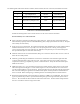
Parts Required Bag #
1 #0015 M2 Hex Nut 12D
1 #0103 M2 x 5 threaded ball 12D
2 #0133 Ball links (long) 12D
1 #0679 M2x170.0 Pushrod 12D
1 #122-98 M4x160mm Graphite Tube 12D
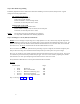
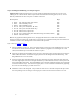
Refer to Drawing #12F
A. Select the #0679 push rod and two #0133 ball links. Install each ball link and adjust to the preliminary
length of 156.0mm. As per your gyro instructions install a control horn with an arm length resulting in a
ball position that is 13-15mm out from the center. Neutralize the servo and temporarily press the arm
onto the servo spline so that the output hole is exactly beneath and on a vertical centerline. Select and
install one #0015 M2 Hex Nut and one #0103 control ball on the outside of the control arm. Snap the
prepared control push rod in place connecting the servo to the rudder bellcrank. The rudder bellcrank
control ball should be in a vertical position at this time. Adjust the control rod if necessary.
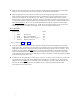
B. Select the #122-98 Graphite Tube. Sand on the end of the tube until its overall length matches the
exposed rod in between the ball links. Remove one ball link. Wipe the pushrod with alcohol and apply
slow CA and epoxy about 10.0mm long at the center of the pushrod. Slide the graphite tube over the
pushrod and re-install the remaining ball link, tightening it fully against the graphite tube. Align each link
in the same orientation and wipe away excess glue. Snap the assembled rod in place.