
Instruction manual


45
Clean the following parts with thinner to remove any oil prior to assembly with Red or Green Locktite:
#0427-1 Bevel Gear
#0541-8 Tail Rotor Output Shaft (shaft portion contacting Bevel Gear)
#0432 M5.0x7.0x3.15 Brass Spacer
#0800-7 Tail Rotor Input Shaft (shaft portion contacting Bevel Gear)
#0425 Ball Bearing (inner diameter only)
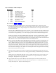
A. Select the #0861-7 13mm Stepped Spacer from the parts bag. (Note: At your option, you may choose to
Amount@ each bearing on the input shaft
with Green or Red Loctite. It is optional at this position and
mandatory elsewhere in the assembly procedure). Slide a #0425 Ball Bearing, the #0861-7 Stepped Spacer,
another #0425 Ball Bearing, and the #0427-1 Bevel Gear onto the #0800-7 Tail Rotor Input Shaft. Press all
parts firmly against the Delrin end piece. Prepare two #0051 M3x3 Socket Set Screws with Blue Loctite and
install them into the gear, making certain that one squarely contacts the Aflat@ on the shaft. Tighten each with
moderate torque. There should be no end play in the assembly.
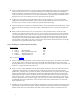
B. Select one #0425 Ball Bearing, the #0431 M5 Circlip, and the #0541-8 Tail Rotor Output Shaft. Snap the
Circlip into place on the shaft. Apply a little Green or Red Loctite to the short end of the shaft and slide a
bearing up against the clip. Allow the Loctite to cure for a few moments before proceeding. The following
procedure will describe the steps for establishing the correct gear position and ultimately applying the
required Green or Red Loctite to the outermost ball bearing. Prepare one #0051 Socket Set Screw with Blue
Loctite. Install it into the #0427-1 Bevel Gear. Slide the gear onto the shaft so that the set screw is located
over the “flat” provided on the shaft and lightly tighten the set screw, only enough to allow the gear to move
along the “flat” on the shaft. Slide the #0432 Brass Spacer and the remaining #0425 Ball Bearing next to the
bevel gear. Slide the shaft assembly (longer end first) into the housing and install the #0861-8 M13 retaining
ring (using the proper tool). Rotate the shaft so that a 1.5mm allen tool can be inserted thru the M3 threaded
hole at the rear of the housing and into the set screw of the bevel gear. Firmly press the long end of the output
shaft towards the #0861-8 Retaining Ring while using the 1.5 allen tool to firmly press the bevel gear in the
opposite direction along the shaft. Tighten the set screw against the “flat” of the shaft while applying this
pressure. Check to see that there is no free-play in the shaft assembly. If there is, repeat the process.
NOTE: A simple test can be performed at this time to determine whether or not to use the #0426 0.005@ gear
shim. Select the previously assembled input shaft. Slide it into the tail rotor housing. Apply a slight amount
of inward pressure and rotate the shaft, noting the feel of the two gears meshing. Now remove the input
assembly and the previously installed output shaft. Loosen the set screws in the gear on the #0541-8 output
shaft. Add one #0426 gear shim to the output shaft assembly as per the drawing. Re-install and adjust the
output assembly as previously done. Once again press in the input shaft assembly. Compare the gear mesh to
the mesh with the shim removed. Choose the smoother of the two possibilities. Remove the input assembly.
Check to see that there is no free-play in the output shaft assembly. Once again remove the retaining ring and
slide the shaft assembly out of the housing. Remove the outer bearing and spacer. Clean the inside of each
with alcohol as well as the output shaft. Apply Green and Red Loctite to the corresponding area of the output
shaft and reinstall the spacer and bearing firmly against the bevel gear. Recheck the tightness of the set
screws. Always keep one set screw tight while adding Loctite to the opposite screw. Reinstall the output shaft
assembly into the gear housing. At your discretion, the O.D. of the #0425 bearings may be green Loctited
inside the gear case. If you Loctite it in place, the disassembly procedure will be more difficult, but the life of
the unit will be extended.