
Instruction manual


11
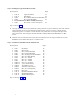
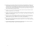
Step 3: Installing the Upper Head Block Assembly
Parts Required: Bag#
1 #122-14 Upper Head Block 1A
1 #122-17 Head Button 1D
4 #0064 M3 x 8 Button Head Socket Head Bolt 1D
2 #0062 M3 x 10 Flat Head Bolt 1D
1 Pre-assembled Lower Block Assembly from Step 1
2 #0687 M3 x 0.086” x 0.158” Steel Spacer 1D
Refer to Drawing #1D
A. The upper head block #122-14 is symmetrical by design, therefore it may be installed on either side. Slide the
upper head block onto the pre-assembled lower block assembly. It may be necessary to lightly tap both
components together. Use a plastic or rubber hammer. If any metal device is used protect the parts with a
piece of hard wood. Secure together with four #0064 M3 x 8 Button Head Socket Head Bolts. Use Blue
Loctite.
B. Install the #122-17 head button to the top of the lower head block #122-15 using two #0062 M3 x 10 Flat
Head Bolts and two #0687 Steel Spacers. Use Blue Loctite.
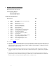
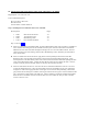
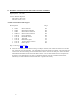
Step 4: Assemble the Main Blade Mounts and Head Axle
Parts Required: Bag #
2 #0011 M5 Washer 1E
2 #0023 M5 Locknuts 1E
2 #0060 M3 x 5 Socket Head Bolt 1E
4 #0061 M3 x 8 Socket Head Bolt 1E
2 #0086 M5 x 12 Flanged Socket Head Bolt 1E
4 #0319 M8 x 16 x 5 Ball Bearing 1E
2 #0329 M8 x 13 x .25 Shim 1E
2 #0331 M8 x 13 x .50 Shim 1E
2 #0426 M8 x 13 x .10 Shim 1E
2 #0840-10 M 8 x 12 x .80 Spacer 1E
2 #0840-12 3-piece Thrust Bearing 1E
4 #0844-2 70-D Rubber O-rings 1E
2 #0848-4 Aluminum retainer sleeves 1E
2 #0848-3 M8 x 12 x 2.0 Hinge Ring 1E
1 #122-02 Head Axle 1E
2 #122-11 Machined Main Blade Mounts 1E
2 #122-12 M5 Main Blade Bolts 1E
2 #122-13 M5 Fiber Blade Spacers 1E
Refer to Drawings #1E
, #1F