
Instruction manual


10
- Medium Pitch to Flybar
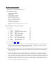
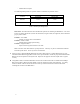
The following Mixing Ratios are possible with the combination of positions chosen:
Flybar Tube Control Ball Location
Bell Mixer Mounting
Location
Inside Hole Outside Hole
Position 1 1:0.61 1:0.56
Position 2 1:0.62 1:0.58
Table 1: Head Input Mixing Ratios
Pitch Arms: Each Pitch Arm has three threaded hole positions for mounting the Bell Mixers. The center
hole is zero offset, the left hole (nearest the main shaft) is negative offset, the right hole (nearest the blade
grip) is positive offset:
Position 1: Zero Offset
- Neutral corrections due to wind influence
Position 2: Positive Offset
- Slightly improved high-speed tracking
Position 3: Negative Offset
- Improved hovering characteristics in the wind
Note: The Pitch Arm offset desired is a pilot preference. This may vary due to combinations of blades
and head speeds chosen. Choice by trial is recommended.
C. Select two #0113 Threaded Double Balls and two #0597-1 Brass Spacers. Install a Brass Spacer on each
Threaded Double Ball and apply Blue Locktite to the exposed threads. Install one prepared Threaded Double
Ball into the chosen position in the Flybar Tube. Repeat for the opposite end of the Flybar Tube. Tighten
securely.
D. Using Blue Locktite, install each Bell Mixer onto the #123-24 Pitch Arms with one #0091 M3x16 Phillips
Bolt and one #0562-1 M3x0.09” Shim Washer. Each unit should pivot freely after tightening. As a safety,
install one #0050-1 M2.5x3 Socket Set Screw into the top side of each Pitch Arm at the chosen offset
mounting hole location of the Bell Mixers.