X-Cell Fury Tempest 3D Instruction Manual Miniature Aircraft p/n #123-100A 1
R/C HELICOPTER SAFETY A radio-controlled model helicopter is a technically complex device that must be built and operated with care. It is also a fascinating and challenging part of the R/C Sport, the mastery of which is very rewarding. A model helicopter must be built exactly in accordance with the building instructions. The kit manufacturer has spent much time and effort refining his product to make it reliable in operation and easy to build.
X-CELL LIMITED WARRANTY The warranty covers defects in material or workmanship or missing components to the original purchaser for 30 days from the date of purchase. Miniature Aircraft, USA will replace or repair, at our discretion, the defective or missing component. Defective components must be returned to us prior to replacement. Any part, which has been improperly installed, abused, crash damaged or altered by unauthorized agencies is not covered.
X-CELL FURY TEMPEST 3-D INTRODUCTION These instructions apply to Fury Tempest Kits #1023-5. Congratulations! You have purchased a quick assembling, high quality helicopter kit ideally suited for beginners through expert pilots. Please pay particular attention to each assembly step. SYSTEM REQUIREMENTS A minimum five channel Ahelicopter@ type radio with electronic swash plate mixing capability (known as C.C.P.M.
High Quality Synthetic Grease (M.A./USA p/n #4707) Light oil (Teflon type M.A./USA p/n #4801) Canopy finishing materials (described elsewhere) 180-220 grit Awet or dry@ sandpaper AC@ clip pliers (both expanding and contracting types) Silicone glue 1.3mm Allen Wrench (M.A. p/n #2964-3) The following are optional tools: Ball link installation tool (M.A./USA p/n #0529) 5.0mm nut driver (M.A./USA p/n #2957-1) 5.5mm nut driver (M.A./USA p/n #2957-2) 7.0mm nut driver (M.A./USA p/n #2957-4) Flybar lock (M.A.
ASSEMBLY INSTRUCTIONS Please take the time to review all instructions and drawings before building the kit. Each step will list bags, tools and parts required to proceed. Any position calling for the installation of steel threaded hardware into non-locking threads will refer to the addition of Blue Loctite thread locker (included). Any position using steel hardware into plastic will refer to the addition of slow Cyanoacrylate glue (CA) (not included) as a thread locker.
ASSEMBLY SEQUENCE SUMMARY Section: Subassembly: I II III IV V VI VII VIII IX X XI XII XIII XIV XV XVI XVII XVIII XIX Building the Rotor head Building the Left Main Frame Installing the Main Shaft, Main Gear and Front Tail Drive Building and Installing the Radio Support Assembly Installing the Right Main Frame, Bell cranks and Gyro Brackets Building and Installing the Landing Gear Installing the Clutch, Fan, and Engine Assembly (Including Guidelines for Engine and Exhaust Selection).
I. BUILDING THE ROTOR HEAD Bags Required: #1A through #1G and Bag #11A Tools or materials required: Small Phillips screwdriver Small hammer Solvent (thinner or alcohol) Loctite B Blue and Green Slow cyanoacrylate glue (CA) M1.3, 1.5, 2.5 and 4.0 Allen tools AQ-Tip@ cotton swabs or tissue Needle nose pliers or forceps A few inches of masking tape 3/8@ or similar socket with an O.D. of 14.0 B16.
D. Select two #0067 bolts and temporarily thread each into holes provided near the base of the head block. Note that even though the holes are threaded full depth, the bolts install from the side closest to the slot at each corner. Do not tighten until Section IX , Step 2F. Step 2: Installing the Bell Hiller Mixers Parts Required: 2 2 2 2 2 2 2 2 4 2 2 #0113 #0597-1 #0109 #0050-1 #123-24 #0597-3 #0115 #123-26 #106-02 #0091 #0562-1 Bag # M3 x 10.5 Threaded Double Ball (long threads) M3 x 0.126” x 0.
- Medium Pitch to Flybar The following Mixing Ratios are possible with the combination of positions chosen: Bell Mixer Mounting Location Flybar Tube Control Ball Location Inside Hole Outside Hole Position 1 1:0.61 1:0.56 Position 2 1:0.62 1:0.58 Table 1: Head Input Mixing Ratios Pitch Arms: Each Pitch Arm has three threaded hole positions for mounting the Bell Mixers.
Step 3: Installing the Upper Head Block Assembly Parts Required: 1 1 4 2 1 2 Bag# #122-14 Upper Head Block #122-17 Head Button #0064 M3 x 8 Button Head Socket Head Bolt #0062 M3 x 10 Flat Head Bolt Pre-assembled Lower Block Assembly from Step 1 #0687 M3 x 0.086” x 0.158” Steel Spacer 1A 1D 1D 1D 1D Refer to Drawing #1D A. The upper head block #122-14 is symmetrical by design, therefore it may be installed on either side. Slide the upper head block onto the pre-assembled lower block assembly.
NOTE: Two different hardness of o-rings dampeners and three sets of shim thickness are included. The specific dampening may vary depending on the main blades chosen or your personnel flying style. We suggest starting with the o-rings and shims described in the following building sequence. -Std. Dampening 4 70-D O-rings (#0844-2) 2 (0.050”) Shims (#0331) -Stiffer Dampening 2 70-D O-rings (#0844-2) 2 80-D O-rings (#0844-) Various combinations of the #0329, #0331, or #0426 Shims A.
C. Repeat step AB@ on the opposite end of the Head Axle. Tighten both #0086 bolts using two 4mm Allen wrenches. D. Slide one #122-11 blade mount into position on the bearing assembly and align the holes with those of the aluminum retainer sleeve #0848-4. On the side of the blade mount with only one hole, install one #0060 M3 x 5 Socket Head Bolt. Only finger tighten at this time. E. Select two Preassembled Pitch Arms from Step 1C and four #0061 M3x8 Socket Head Bolts.
II. BUILDING THE LEFT MAIN FRAME Bags Required: #2A, #2B, and #3D Tools or Materials Required: M2.5 Allen Tool M5.5 (7/32@) flat wrench M7.
D. Install the #115-12 Vertical Front Channel using one #0061 M3 x 8 Socket Head Bolt, one #0063 M3 x 10 Socket Head Bolt and one #0019 M3 Locknut. The open side of the channel faces forward. Temporarily install the #0063 M3x10 Socket Head Bolt into the fifth hole from the bottom of the frame in the location for the channel as shown. Temporarily lightly tighten the bolt so the channel can be aligned at the bottom.
III. INSTALLING THE MAIN SHAFT, MAIN GEAR AND FRONT TAIL DRIVE Bags Required: #3A, #3B, #3C, #7D Tools or Materials Required: M1.5, 2.0 and 2.5 Allen tools M5.5 flat wrench Tri Flow #4801 or similar Teflon oil Step 1: Installing the Front Tail Rotor Drive Gear and Shaft Parts Required: 3 1 1 1 #0051 #0232 #0237 #120-9 Bag # M3x3 Socket Set Screws 15 Tooth Bevel Gear M5 Retaining Collar Front Transmission Shaft 3A 3A 3A 3A Refer to Drawing #3A A.
Step 2: Assemble the Constant Drive Autorotation Upper Section Parts Required: 8 1 1 #0088-1 #0866-5 #0866-6 Bag# M3x5 flat head screws 70-Tooth Upper Bevel Gear Upper gear mounting base w/main shaft sleeve 3B 3B 3B Refer to Drawing #3B Select eight #0088-1 M3x5 Flat Head Screws and prepare each with Blue Loctite. Select the #0866-5 Bevel Gear and #0866-6 Mounting Base. Press the mounting base downward into the upper surface of the bevel gear, aligning the holes as you proceed.
Step 4: Installing the Main Shaft and Main Gear/Autorotation Assembly Parts Required: 1 2 1 1 1 1 1 1 1 1 2 1 #0057 #0059-1 #120-10 #0840-6 #0865-6 #0865-7 #0866-10 #0866-11 #0866-12 #0866-13 #0875-1 #115-22 Bag# M4x4 socket head set screw M2.5x6 Socket Head Bolts Main shaft M3x20 dowel pin M10.1x15.8x0.1 shim ring M10.1x15.8x0.2 shim ring M14.0x20.0x0.2 shim ring M14 Teflon o-ring Retaining collar (black) M14.0x20.20x0.1 shim ring Split type main shaft collars M10.1x11.1x7.
O-rings, and the shim(s). Apply a little grease to each side of the shim(s) and reinstall all items except the dowel pin. NOTE: Concerning step AF@ below, it may be necessary to loosen the lower main shaft block #115-18 to allow the main shaft to slide into the bearing easily. Re-tighten the bolts after the main shaft has been tightened. E. Slide the autorotation unit into position and slide the main shaft downward.
IV. BUILDING AND INSTALLING THE RADIO SUPPORT ASSEMBLY Bags Required: #4A, #4B Tools or Materials Required: M2.0 and 2.5 Allen tools M5.5 flat wrench (7/32@) Assemble and Install the Radio Support Parts Required: 4 2 1 2 1 1 1 1 1 2 #0019 #0064 #0089 #0840-31 #106-41 #115-24 #123-32 #115-28 #115-30 #115-32 Bag # M3 hex locknuts M3x8 button head bolts M3x10 flat hex head bolt M3x16 button head bolts Canopy Standoff Horizontal channel Tank plate Radio/battery plate 16.0x305.
B. Select the #115-28 Radio/battery Plate, the #115-30 Velcro Strip, two #0840-31 M3x16 Button Head Bolts, two #115-32 Plastic Spacers and two #0019 M3 Hex Locknuts. At this time, it is suggested to make a determination of final battery position for correct model C.G. Two positions are possible on the radio/battery plate. In general, you=ll want to locate the plate in the forward position using the most narrow bolt spacing. C.
V. INSTALLING THE RIGHT MAIN FRAME, BELL CRANKS AND GYRO BRACKETS Bags Required: #5A through #5E Tools or Materials Required: M1.5, 2.5 Allen tools M5.5 and 7.
Step 2: Installing the Right Main Frame Parts Required: 1 9 4 2 2 3 1 1 1 2 #0064 #0061 #0063 #0019 #0089 #0060-1 #0169 #106-41 #122-27 #0009 Bag # M3x8 Button Head Socket Head Bolt M3x8 Socket Head Bolt M3x10 Socket Head Bolt M3 Locknut M3x10 Hex Head Bolt M3x6 Socket Head Bolts Bell Crank Pivot Stud Canopy Standoff Rear Canopy Hex Spacer Mount M3 Washers 5C 5C 5C 5C 5C 5C 5C 5C 5C 5C Refer to Drawing #5B NOTE: Use Blue Loctite on all hardware except the #0019 M3 Locknuts and corresponding Socket Head
L. Tighten all components securely unless otherwise noted. Step 3: Assemble and Install The Aileron Bell Cranks Parts required: 2 2 2 2 2 #122-33 #122-35 #0051 #0115 #0109 Bag # Aileron Bell Cranks w/ Bearings Bell Crank Collars M3 x 3 Socket Set Screws M3 x 10.5 Threaded Ball M3 x 8 Threaded Ball 5D 5D 5D 5D 5D Refer to Drawing #5C A. Refer to the drawing for orientation of the threaded balls in each bell crank.
1 #0019 M3 Locknut 5E Refer to Drawing #5D A. Select two #0636 Flanged Ball Bearings, one #0862-4 Brass Spacer Ring, and one #0862-2 Rudder Bell Crank. Press one bearing into one side of the bell crank, insert from the opposite side one #0862-4 Brass Spacer Ring followed by the remaining bearing (the brass spacer will limit full insertion of the second bearing by 0.03-0.04mm to prevent bearing damage after installation on the standoff). B.
VI. BUILDING AND INSTALLING THE LANDING GEAR Bags Required: #6A and #6B Tools or Materials Required: M2.5 Allen tool Small Phillips screwdriver Hand drill with 2.35mm (3/32@) drill Small hammer Slow Cyanoacrylate glue (CA) M5.
D. Examine the drawing and note the orientation of the parts as they attach to the main frame assembly. The main frame assembly will slide downward into the channel formed at the top of each #115-40 Landing Gear Mount. Select four #0065 M3x12 Socket Head Bolts and four #0019 M3 Hex Locknuts.
VII. INSTALLATION OF THE CLUTCH, FAN AND ENGINE ASSEMBLY (INCLUDING GUIDELINES FOR ENGINE AND EXHAUST SELECTION) Bags Required: #7A through #7F Tools or Materials Required: M2.5 and 3.0 Allen tools M5.5 (7/75@) flat wrench Light oil AThin wall@ (12 point) socket and ratchet to fit the crankshaft nut of your chosen engine 6.0-7.
Guidelines for Exhaust System and Fuel Selection Many choices in exhaust systems are available and their performance is directly related to the choice of fuel. Always use the highest quality Ahelicopter only@@ fuel. The nitro-methane content is an important factor in choosing an exhaust system.
Y.S. .91H Qty: 1 1 1 1 1 1 1 M.A. USA p/n #0619 #0546-6 #0579-4 #0546-11 #0331 Description: Stock Washer M10 x 16 x .50 Shim Base collet Cooling Fan Hub Upper Collet M8 x 13 x .50 Shim Hex Nut Step 1: Installation of the Fan Hub Assembly On the Engine Parts Required: 2 1 2 1 1 2 1 1 1 #0078 #0546-6 #0546-16 #0579-4 #0546-21 #0331 #0546-5 #0546-11 #0619 Bag # M4x12 Socket Head Bolts Base collet (9.5mm I.D.) Molded Rubber Dampeners Fan/hub Assembly Fan Tool M8.0x13.0x0.5 Flat Washers Collet (8.0mm I.D.
the hub. They sit Aflush@ or within 0.25mm of the top surface of the hub. Step 2: Installing the Clutch Assembly Parts Required: 20 8 1 1 8 #0009 #0063 #122-44 #115-45 #0065 Bag # M3 Flat Washers (small) M3x10 Socket Head Bolts Clutch/Lower Bearing Block/Clutch Driver Assembly M6 O-ring M 3x12 Socket Head Bolt 7C 7C 7C 7C 7C Note: Select the following parts from Bag #7D appropriate to your model’s Gear Ratio: 7.
C. Select the twenty #0009 M3 Washers, eight #0063 M3x10 Socket Head Bolts, and eight #0065 M3x12 Socket Head Bolts. Place one #0009 M3 Washer on each bolt, including the bolts from Step B. D. Install the Clutch/Clutch Bell unit in place between the main frames. Examine the drawing and note the position of the #0063 M3x10 Socket Head Bolts and the #0065 M3x12 Socket Head Bolts through the doubler plates and into the clutch unit. Lay one Graphite Doubler Plate in position on the left main frame.
A. Select four #0003 M3 Flat Washers (large), four #0019 M3 Hex Locknuts, and four #0067 M3x14 Socket Head Bolts. Additionally, select one each #119-50 Left Motor Mount and #119-51 Right Motor Mount. Examine the drawing and note two 3.0mm holes (ahead of the vertical slots) passing through each side frame and the #115-12 Vertical Front Channel. Prepare four #0067 M3x14 Socket Head Bolts by installing one #0003 M3 Flat Washer on each.
Step 4: Installing the Fan Shroud and Switch Plate Parts Required: 5 2 2 2 2 1 4 2 1 4 2 2 #0029 #0032 #0061 #0063 #0079 #0548-5 #115-58 #115-60 #123-34 #3923-1 #0065 #0060-1 Bag # M2.2x13.0 Phillips self-tapping screws M2.9x9.5 Phillips self-tapping screws M3x8 Socket Head Bolts M3x10 Socket Head Bolts M3x35 Socket Head Bolts Left and right fan shroud Fan shroud braces M5.75x27.5 carbon tubes Switch plate M4.0x14.6x4.
enough to allow adjustment. D. Select both halves of the #0548-5 Fan Shroud and two #0029 M2.2x13 Phillips self-tapping screws. Examine the drawing and slide each half of the shroud in position between the previously installed braces. While loosely sitting within the frames, install the two #0029 screws (one front and one rear, from the left side) to hold the shroud halves together.
VIII. BUILDING AND INSTALLING THE FUEL TANK ASSEMBLY Bag Required: 8 Tools or Materials Required: Modeling knife or razor blade 8.0mm (5/16@) flat wrench 2.25mm diameter (.086@) drill bit (optional) Small pliers or vice grips (optional) Forceps (hemostats) (optional) Premium grade fuel filter(s) (two in all cases except Y.S.
clunk, always maintain the exact length of 73.0mm. Frequency of service should be every six to ten gallons of fuel burned (depending on the variables mentioned). B. Insert the prepared fuel pick-up tube, clunk and fitting (from inside the tank) out through the hole supplied in the side of the tank and secure with one #0409 90 degree external tank fitting. Tighten securely resulting in the 90 degree fitting pointing rearward. A 5.5mm hex is provided on the pick-up fitting to aid in tightening.
IX. INSTALLING THE SWASHPLATE, WASHOUT UNIT AND ROTOR HEAD ASSEMBLY Bag Required: 9A Tools or Materials Required: M1.5 and 2.5 Allen tools Medium Phillips screwdriver Small good quality pliers Small flat screwdriver Step 1: Assembling the Swashplate Parts Required: 1 4 1 3 4 1 1 1 #0009 #0051 #0065 #0107 #0109 #0159 #0217 #0597-3 Bag # M3 flat washer (small) M3x3 socket set screws M3x12 socket head bolt M3x6 threaded balls M3x8 threaded balls M3x7 ball bearing Swashplate M3.0x4.75x4.
Step 2: Assembling the Washout Unit Parts Required: 1 2 2 4 1 2 2 1 2 2 5 #0057 #0097 #0107 #0159 #0219 #0221 #0597-2 #0840-6 #0869 #106-07 #106-08 Bag # M3x3 Socket set screw M3x 22 Special Phillips 12.9 Hard Bolt M3x6 Threaded Ball M3x7 Ball Bearings Plastic Washout Hub Washout Arm M3x3.4 Brass Spacer M3x20 Dowel pin Washout ball links M2x16 Pivot pins M2 Circlips 9B 9B 9B 9B 9B 9B 9B 9B 9B 9B 9B Refer to drawing #9A A.
C. Select two #0869 Washout Ball Links, two #106-07 M2x16 Pivot Pins, and four #106-08 M2 Circlips (a spare is also included). Note: The #106-08 Circlips are most easily installed on the #106-07 Pivot Pins by the following method: Lay the circlip on a flat surface. Hold the #0106-07 Pivot Pin with a pair of pliers, while aligning one end of the Pivot Pin vertically on top of the circlip. Tap the opposite end of the Pivot Pin with a small hammer into the circlip.
X. BUILDING THE TAIL ROTOR ASSEMBLY Bags Required: #10A, #10B, and #10C Tools or Materials Required: M1.5 Allen tool M6.0 socket nut driver M7.0 (9/32@-5/16@) socket (optional) Small hammer Small Phillips and straight screwdrivers Grease Retaining Ring Pliers Green Loctite Step 1: Assembling the Tail Rotor Hub and Blade Holders Parts Required: 2 2 2 2 2 2 2 1 #0019 #0021 #0097 #0446-4 #0457 #0873-1 #120-39 #122-65 Bag # M3 Locknuts 10A M4 Locknuts 10A M3x22 Special 12.
C. Select the #122-65 Steel Tail Rotor Hub, one #0873-1 Tail Rotor Blade Mount, the remaining #0457 Thrust Bearing components, one #0446-4 M4 Shim Washer, one #0021 M4 Locknut and a 7.0mm socket or nut driver. While holding the tail hub in a vertical position, slide one of the #0873-1 Tail Rotor Blade Mount assemblies onto the T/R hub, followed by one #0446-4 0.003” shim. Using a small screwdriver or toothpick, apply Green Locktite to the threaded portion of the #0021 M4 Locknut.
A. Select one #0101 M2x5 Threaded Ball and one #0437 Plastic Pitch Ring. Install the Threaded Ball into the Plastic Pitch Ring, use a small amount of slow CA glue. Do not over tighten. B. Select two #0439 Ball bearings. Place each on a clean surface, “ball” side up and add grease. Press one into each side of the #0437 pitch ring so that the “ball” sides face inward. C. Select the #0435 Tail Rotor Pitch Slider. Examine the previously prepared #0437 Plastic Pitch Ring.
Step 3: Assembling the Tail Rotor Gear Box Materials and Tools Required: M1.5 and 2.5 Allen (Hex) tools A inside type@ Retaining ring pliers Green, Blue and Red Loctite Suitable grease with thin nozzle or Aspring type@ applicator (M.A.
Clean the following parts with thinner to remove any oil prior to assembly with Red or Green Locktite: #0427-1 #0541-8 #0432 #0800-7 #0425 Bevel Gear Tail Rotor Output Shaft (shaft portion contacting Bevel Gear) M5.0x7.0x3.15 Brass Spacer Tail Rotor Input Shaft (shaft portion contacting Bevel Gear) Ball Bearing (inner diameter only) A. Select the #0861-7 13mm Stepped Spacer from the parts bag. (Note: At your option, you may choose to Amount@ each bearing on the input shaft with Green or Red Loctite.
C. Select the previously assembled input shaft. Slide it into the tail rotor housing. NOTE: There are two M3 threaded holes at 180 degrees apart on the housing inlet. Install one M3x3 set screw very lightly to provide a little friction against the input shaft spacer #0861-7. Set the desired gear mesh and tighten the set screw. Install the remaining set screw and tighten.
XI. BUILDING THE TAIL BOOM ASSEMBLY, BOOM SUPPORTS, AND INSTALLATION ONTO THE MAIN MECHANICS Bags required: 11A through 11D Tools or materials required: M1.5 and 2.5 Allen tools M5.5 (7/32@) flat wrench Small pliers Small straight blade and Phillips screw drivers Hand drill with 1.30mm (.055@) drill bit Heat gun AJ-B Weld@ epoxy or similar slow cure epoxy, slow Cyanoacrylate glue (CA) and silicone glue Small piece of 180 - 22- grit sandpaper Light oil or Vaseline petroleum jelly.
C. Select two #0006 M2.5 Atoothed@ Lock Washer, four #0015 M2 Hex Nuts, two #0043 M2x12 Slotted Machine Screw, two #0477 Push Rod Guide Supports, and two #0868-5 Push Rod Guides. Wrap the #0477 support around the boom as shown in the drawing and install one #0043 screw from above and a #0015 Hex Nut from below. Tighten only enough to allow adjustment.
Step 2: Installing the Tail Boom Supports Bag# Parts Required 6 2 4 2 2 4 1 2 1 2 #0003 #0093 #0048 #0872-5 #3923-1 #0872-2 #0065 #0009 #0019 #0079 M3 Washers B Large M3x18 Phillips Bolt M3.5x25 Socket Set Screw Graphite Tubes 25@ Plastic Round Spacers Molded Boom Support Ends M3x12 Socket Head Bolt M3 Washers B Small M3 Locknut M3x35 Socket Head Bolts 11C 11C 11C 11C 11C 11C 11C 11C 11C 11C Refer to Drawings #11C and #11C-1 A. Select four #0048 M3.5x25 Socket Set Screws and two #0872-5 Graphite Tubes.
E. Select two #0003 M3 Flat Washers, two #0093 M3x18 Special Phillips Bolts, and the two prepared graphite tubes (from the previous step). It is suggested that both braces be aligned and fitted prior to final gluing. Install one washer on one #0093 bolt and insert into one brace end. With the graphite tube pointing forward, temporarily thread the bolt and brace into one of the molded holes on either side of the horizontal fin mount.
surpass the length of either Teflon tube. Mark the position of each and disconnect both ball links so that the pushrod and Teflon tubes can be moved away from each guide. Use a heat gun to shrink each Teflon tube and reinstall the pushrod in its proper location.
XII. INSTALLING THE RADIO SYSTEM AND PUSHRODS Bags required: #12A through #12G Tools or materials required: Small Phillips screw driver 1.5mm Allen tool Small pliers or forceps 4 large heavy duty servo wheels or arms (J.R. Super Servo Horn set - purchased separately) (Futaba - 45.
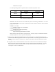
The following table will indicate the Servo Number, Frame Position, Receiver Connection, and Model Connection: Servo Number Frame Position Receiver Connection Model Connection 1 Top of Right Frame Elevator Rear Bellcrank 2 Second from Top of Left Frame Aileron Left Front Bellcrank 3 Third from Top of Right Frame Pitch Right Front Bellcrank 4 Fourth from Top of Left Frame Rudder Rudder Bellcrank 5 Fifth from Top of Right Frame Throttle Carburetor Table 2: Servo Location and Installati
Step 2: Basic Radio Programming Preliminary adjustments must be made to the radio before installing servo arms (wheels) and push rods. Typical settings are listed for popular radios. J.R. X 8310/ PCM 10 Series Select swash type function 65. Select 120 C.C.P.M. function. Retain all Adefault@ C.C.P.M. settings of 60%. Set aileron, elevator and pitch ATV at 100%. Futaba 8 UHP / 9 CH / 9 ZH Select SR3 swash type in Amodel@ menu. Retain Adefault@ settings at 60% for aileron, elevator and pitch.
A. Select the #122-95 push rod and two #0133-1 ball links. Install each ball link and adjust to the preliminary length of 112.7 mm (measured as the amount of push rod exposed between the ball links). B. Select the appropriate servo arm (wheel), neutralize the servo and temporarily press the arm onto the servo spline so that the output hole is exactly above and on a vertical line 2.5 degrees rearward from a vertical center line with the hole for the arm retaining screw.
Servo #4 Parts Required 1 1 2 1 1 #0015 #0103 #0133 #0679 #122-98 Bag # M2 Hex Nut M2 x 5 threaded ball Ball links (long) M2x170.0 Pushrod M4x160mm Graphite Tube 12D 12D 12D 12D 12D Refer to Drawing #12F A. Select the #0679 push rod and two #0133 ball links. Install each ball link and adjust to the preliminary length of 156.0mm. As per your gyro instructions install a control horn with an arm length resulting in a ball position that is 13-15mm out from the center.
Servo #5 Parts Required 2 2 2 1 #0015 #0103 #0133 #0373 Bag # M2 Hex Nut M2x5 Threaded Ball Ball links (long) M2x130 Pushrod 12E 12E 12E 12E Refer to Drawing #12G A. Select two #0133 ball links and the #0373 Pushrod. This push rod has extended threaded surfaces and may be too long for some applications. To determine the correct length, measure the exact distance from the Servo #5 (throttle) spline hole to the center point of the carburetor barrel. Subtract 18.0mm from this distance.
Step 4: Installing the Swashplate Lower Push Rods Parts Required 6 3 #0133 #0227 Bag # Ball links (long) M2x42 Pushrods 12F 12F Refer to Drawing #12H Select six #0133 ball links and three #0227 Pushrods. Install two links on each push rod, adjusting each until approximately 26.0mm (if calipers are used, make them 25.2mm each) of pushrod is exposed between the links. Snap each prepared pushrod onto each control ball on the outer swash plate ring and the corresponding bellcrank below.
Step 6: Installing the Ball Bearing servo Output Supports Important Note: Futaba and Hi-Tech servos require an M2.6 threaded fastener/bearing pivot (#115-73) for retaining the servo wheel and J.R./Sanwa require an M3.0 threaded fastener/bearing pivot (#115-74). Do not make any substitutions for the correct parts or a failure could occur. Parts Required 4 2 6 4 4 2 6 4 8 #0016 #0037 #0037-1 #115-73 #115-74 #115-80 #115-82 #115-86 #0560-8 Bag # M3 Ainternal toothed@ lock washers M2.5x25 Phillips screws M2.
XIII. PREPARING THE CANOPY Bag required: 13A Tools or materials required: Slow cyanoacrylate glue (CA) (Optional) Painting materials (See text supplied with the decal sheet) NOTE: Refer to the ASuggested locations for decals@ sheet. Drill holes and cut out areas as shown. Painting can be done before or after the following steps but trial fitting is suggested.
Step 2: Canopy Finishing Suggestions At your option, the canopy can be used in the Awhite@ form provided or painted to your choice. If overall painting is chosen, these instructions assume you have the necessary experience and materials therefore only the steps required to finish the canopy in Awhite@ are described below. Note: If you are changing the color, be aware that the decals are best applied only over white or very light colors. NOTE: Refer to Table 3: Finishing Methods and Procedures.
Table 3: Finishing Methods and Procedures Painting Characteristics: Finish Choice: Clear-coat Method Non Clear-coat Method Longer completion time, high gloss, best decal Quicker completion time, shorter decal life, protection, slightly increased weight lightest weight Procedures Step (1) Wash thoroughly with warm water and detergent Wipe with alcohol or paint prep solution Note: The canopy can be left as is or further detailed.
XIV. ROTOR BLADE SELECTION It is recommended that a blade length of 680mm to 700mm be used. A good quality rotor blade is suggested. Miniature Aircraft USA offers a variety of high quality rotor blades suitable for the Fury Tempest. XV. FINAL MECHANICAL AND ELECTRONIC SET-UP NOTE: The following procedures will be described using a pitch gauge, fly bar lock and paddle gauges. The use of these items is highly recommended since without them an accurate set-up is very difficult.
Table 4: Initial Pitch/Throttle Settings Desired Flying Style/Type Throttle/Collective Low Stick Position Throttle/Collective Half Stick Position Throttle/Collective Full Stick Position Rotor Head RPM Basic Flying and Hovering -2° (20%)* +5° (50%) +8° (90%) 1500 Mild Aerobatics/Autorotat ion (Idle-up 1) -4° (60%) +4° (60%) +10° to +11° (100%) 1700 to 1800 3-D Flying (Idle-up 2) -10° to -11° (100%) 0° (50%) +10° to +11° (100%) 1700 to 1800 *(Percentages Shown are Approximate throttle sett
XVII. PRE-FLIGHT INFORMATION At home: Be sure you have all necessary equipment to operate or service the model. Be sure all batteries are fully charged. At the flying site: Observe any flying site rules. Check the frequency board or nearby pilots to clear your frequency. Range check your radio as per the manufacture=s instructions. Pre-check all controls. Obtain assistance from more experienced pilots of possible.
XIX. FIRST FLIGHT ADJUSTMENTS Before flying double check direction of each control; tail rotor compensation direction and gyro direction. The first few flights should be limited to hovering only. Engine Carburetor Settings: With the engine running, set the idle adjustments to enable the engine to maintain a rich reliable idle (trying to four cycle) at low throttle, mid to high trim. Set the high speed needle to accelerate, but slightly rich.
We wish you good luck and many happy hours of flying! If you have any further questions, feel free to call us. MINIATURE AIRCRAFT USA 31713 Long Acres Drive Sorrento, Fl 32776 PHONE (352) 383-3201 FAX (352) 383-3204 WEB SITE: www.miniatureaircraftusa.com Email: minair@earthlink.
Tempest 3D Instruction Manual Document Revisions Rev 1 – Initial Issue 06/24/2003 SEK Rev 2 – changes per T. Schoonard 06/04/2003 SEK Rev 3 – Changes to boom support assy 06/27/2003 SEK Rev 4 – Update Anti-rotation assy to include the washers. Update parts count of links in head push rod assy. 08/05/2003 SEK Rev 5 – Change tail rotor bellcrank p/n. Change tail rotor pushrod length (156mm). Update anti-rotation unit to one piece assembly.