SECTION 3 VITALSENSE OPERATION APPLICATION PROGRAM CHAPTER 3 Introduction The VitalSense Application Program is a software utility that communicates with the VitalSense Monitor via an RS-232 cable. With this link, a variety of functions can be accomplished from the host PC.
PC Preparation Prior to Installation PC Requirements for VitalSense • IBM®-compatible PC • Pentium® II processor with a clock speed of at least 350 MHz • 64 MB of RAM • Windows® ‘98, 2000, XP, Millennium, or Windows NT 4.
Installation of Software NOTE: Before beginning the installation procedure, make sure that no other applications are currently running on the host PC. This includes MS Office® and any other utilities. These can interfere with proper installation, resulting in software conflicts. The VitalSense Application Program software is distributed as a MicroSoft® Installation package (.msi) file. If you have Windows® 2000 or XP, simply double-click on the filename and follow the instructions.
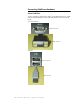
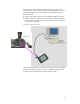
Connecting VitalSense Hardware Serial COM Port Today’s computers typically have either a 9-pin DB9 serial port or a USB (Universal Serial Bus) port. These will look similar to the ones pictured below.
The 9-pin serial cable is the type supplied with your system. If your computer does not have a 9-pin serial port, it is suggested that you obtain a 9-pin to USB adapter. These are available at most computer supply or electronics stores. 1 Plug the 9-pin DB9 connector into an available COM port on the PC. 2 Plug the miniature 5-pin barrel connector into the VitalSense Monitor. For proper insertion, align the dot on the barrel connector with the dot on the monitor connector.
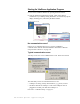
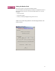
Starting the VitalSense Application Program 1 Turn on the VitalSense Monitor by pressing the Power button. 2 Start the VitalSense Application program. Click on the shortcut established on your desktop during installation. An introductory splash display should appear, followed by the Main window. VitalSense shortcut icon Splash display Main window No communication errors? If there are no communications errors, you have established communications with the VitalSense Monitor.
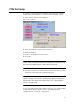
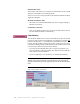
COM Port Setup If necessary, you may change the COM port with which your computer communicates with VitalSense, as well as baud rate and flow control. 1 Click on Setup, then click on COM Port. Main > Setup > COM Port 2 Select the COM port using the drop-down menu. 3 Select the baud rate. 4 Check or uncheck the Flow Control box. 5 Click OK. NOTE: The recommended (and factory defaults) for baud rate and flow control 57,600 and flow control OFF respectively. 6 Attempt to communicate with the monitor.
Monitor Setup for Data Collection Setup for Data Collection from the VitalSense Application Program is very similar to portions of “ VitalSense Monitor Operation ” on page 2-1. This section, however, contains instructions on additional functions, such as retrieving data and real-time observation of data collection. Before data collection can begin, the monitor must be set up, or configured. This configuration can be done from the host PC through the RS-232 port of the monitor.
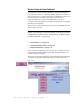
Setting the Monitor Clock The Clock Setup is accessed from the Main window. To void confusion, the following steps should be accomplished in order. If done in this manner, the UTC clock will automatically be set as well as local time. • Set the local time. • Set the UTC Offset. • Check (or uncheck) Daylight Saving Time Auto-set. NOTE: You cannot change Monitor Clock Settings functions with sensors on-line.
Read Monitor Clock This function will enable you to read the on-board monitor clock, and will display it in the Monitor Clock Settings fields. There are two ways to change the time in the VitalSense Monitor from the Application Program. Manually Set Monitor Time • Selectively set each field individually, then click on Apply Settings to Monitor Clock button. Set Monitor to PC Time • Click on Set Monitor Clock to PC Clock. The PC time will be entered into the VitalSense Monitor automatically.
Subject Information Subject Information is the identification information that the practitioner can download to the VitalSense Monitor using the Application Program. The VitalSense Application Program uses a wizard to gather subject information. This wizard is accessed from the Setup window. The Subject Information is provided to identify the monitor and data collection session, therefore only one Subject is possible. This wizard will assist you in assigning subject information.
2 The wizard will suggest you download any previously acquired data, and then gives you the opportunity to erase the data memory. By clicking on Next and the confirmation prompt Yes, the data memory will be erased. The subject and sensor data will remain. Data memory erasure 3 Entering a new subject, however, will result in the erasure of any previous subject and sensor information.
4 New subject data can now be entered. Age and date of birth may be entered using the arrows, or double-click-and-enter in each field. 5 Click Finish to complete the entry.
Sensors Sensor logging may be toggled on or off, or the sensor dropped from the activated sensor list. Follow the prompts as shown below. Drop Sensor Drop Sensor from Sensor Summary Table 1 From the Main menu, click on Sensors. 2 Check the Drop boxes of the sensors you want to drop from the activated list. 3 Click on Drop Selected. The sensor will no longer appear on the Sensor List. To acquire the sensor list on the VitalSense Monitor, press the Data Views button on the front panel.
Logging On/ Off Data Logging On or Off This function turns the logging function of the VitalSense Monitor on or off. This effects data collection on all sensors, without regard to which sensors have been selected in the Activated Sensor Table (see previous function). 1 From the Activated Sensor Table, click on Sensor Options. 2 Click on Data Logging On or Off. 3 Click OK or Apply to enter your selection.
Read Data This function retrieves recorded data from the VitalSense Monitor. 1 Read is accessed from the Main window. Click on Read. Main Display 2 You will be prompted to name the file where this data are to be saved, and select a location. You may either type in the path or use the browser to select the location. Read data 3 The data may be saved as a VitalSense Binary File (.vsb), the default, or a text file (.txt). Name the file, choose its location, and click on Save.
A Data Collection Summary will appear. This is essentially an “index” of the data collected. Data Collection Summary NOTE: If you choose not to generate a report at this time, you may use the Open File command and generate a report at a later time. VitalSense Data Collection Summary The table of sensors as shown above contains the following information for each sensor listed: • Extract - Check box that selects the data that will appear in the report. • Sensor ID - Number assigned sensor at factory.
• Data Collected in Medic Mode™ - When checked, lost packet detection is disabled, since it is unknown when a packet is expected to arrive. (Medic Mode is a VitalSense Monitor option.) • Generate Report - Begins the file extraction and decoding process. • Cancel - Disables the extraction and decoding process. Generate Report This function will generate two files (explained below). 1 Choose the sensors that will appear in the report. 2 Click on Generate Report.
NOTE: The report will generated and then written by default to the same location as the raw data (.vsb) file. You must have Write permission for that directory. The following is an attempt to read a .vsb file from a CD. The VitalSense Application Program asks for another destination for the report because it cannot write to a CD. Prompt to change report destination Output Files Two output files will be generated. Both files will be named with the original Read Data filename.
Monitoring Data in Real Time Monitoring in Real Time allows data collection to be observed as it is being saved. 1 From the Main window, click on Real Time. 2 You will be asked where the information is to be saved, and to name the file. Once named, click OK. 3 The following window will fill as the data begin to be retrieved. NOTE: There is a delay of one sample interval in the time the data appears on the PC display. Real-time data 4 Click Close to stop the observation in real time.
Application Program Options Firmware Version Clicking on this feature will query the monitor for the firmware version currently on board the VitalSense Monitor. This information is particularly useful when calling Mini Mitter for Technical Support. Main > Setup > Options Display Time The two buttons enable either the local time or UTC time to be shown on the display.
Update Firmware Periodically new firmware may be released by Mini Mitter Company, Inc. These releases may be made by CD, Website, e-mail, or other means. Without regard to the distribution, the following process is to be used to upgrade the firmware. This procedure will erase all portions of the VitalSense monitor memory. All setup and data information will be lost. If data are in the memory, you must download prior to beginning the upgrade procedure.
4 Click on OK. Progress can be verified from the PC and the monitor. Once downloaded, the firmware upgrade will be verified. When verified, a prompt will confirm that the upgrade is completed. Download progress Clear Memory See “ Clear Memory ” on page 3-10.
Establishing RS-232 Communications - Advanced When there is a failure to communicate via the serial RS-232 cable, typically the cause is one of two major COM port errors: • COM port is already in use. • General communication errors NOTE: This following procedure requires modification of the configuration file. If you are inexperienced or uncomfortable with this procedure, contact your System Administrator for assistance. COM Port Already in Use The VitalSense Application Program default COM port is COM1.
General Communication Error In this type of error, the program can open the serial port, but cannot establish communications with the VitalSense Monitor. COM port advisory 1 Check the serial cable connection at the PC, and at the VitalSense monitor. 2 Verify the default baud rate of the VitalSense Monitor is set to 57.6 kilobaud. This can be found from the monitor front panel. Use the following path: Setup > RS-232 Interface > Baud Rate: 57.6k If it is not, use the arrow buttons to select 57.
USB Adapter Persistent RS-232 Errors If you still have difficulty establishing communications with the VitalSense Monitor, it may be necessary to use a USB to serial adapter. Some brands of laptops have demonstrated peculiar problems due to hardware and/or driver incompatibility. The use of a USB-to-serial port adapter will require you to install the new driver supplied with the adapter, and this may result in successful communication.
SECTION 4 MAINTENANCE CHAPTER 4 This section applies to the VitalSense Monitor, including hardware maintenance such as battery replacement and cleaning. The VitalSense Monitor uses a very specific battery. When replacing the battery, use only a lithium 3.6 volt AA-size battery (SAFT LS 14500). Any battery other than the one specified may cause damage to the circuitry of the VitalSense Monitor, or cause reduced performance. Do not attempt to recharge the lithium battery.
Low Battery Conditions Low Battery Warning Icon A low battery condition will be indicated on the front panel display by a low-battery icon. This is not a “fuel gauge,” i.e., it means that the battery level has dropped below a set point and should be changed. Low battery icon If attempting to activate sensors during a low battery condition, the following cautionary statement may appear. An attempt to activate sensors during this condition may result in the monitor shutting down.
The following display means that the monitor is no longer functioning other than displaying the following LCD warning. Data collection has ceased, but may continue if the battery is replaced quickly (less than one hour). 1 Press the Power button to power down the VitalSense Monitor. 2 DO NOT remove the battery until you have a replacement at hand. The residual power in the battery may be enough to retain time-keeping information. 3 When a replacement is available, install a fresh battery.
Battery Replacement 1 Press the Power button to turn the VitalSense Monitor off. 2 The VitalSense Monitor battery is located in the battery compartment, accessible from the bottom of the monitor as shown below. Monitor battery compartment 3 Unscrew the battery compartment cover. If necessary, you may use a coin or screwdriver. Remove the lithium cell. Do not dispose of lithium batteries in fire or flame. An explosion may result.
4 Replace the battery as shown below, with the positive end inserted first. Replacement battery inserted 5 Replace the battery compartment cover, and finger-tighten. Do not over-tighten. 6 Press the Power button to turn the monitor power on. NOTE: If sensors are active, VitalSense will reestablish communication with them and begin data acquisition. This may take a few minutes. Calibration Sensors Sensors are factory calibrated and do not require user to enter calibration values.
Storage Although the shelf-life of the monitor battery is extremely long, it is recommended that the battery be removed if the monitor is to be placed in storage for more than 180 days. Cleaning Cleaning of the VitalSense Monitor can be accomplished by wiping the surface with a soft, damp cloth. A mild detergent and water can be used to remove dirt and stains. Do not use abrasives or alcohol. The seals and display may be damaged. Also see “ Sanitizing VitalSense Components ” on page -xiii.
SECTION 5 VS-XHR HEART RATE SENSOR Read the material at the end of this section for indications, contraindications, cautions, and warnings with regard to the VS-XHR Heart Rate Sensor and the associated re-charging devices. Description VS-XHR is a cardiac monitor sensor, used to detect, measure, and transmit Heart Rate and Respiration Rate values to the VitalSense Integrated Physiological Monitoring System (VS-IPMS).
Charging the VS-XHR Sensor Read “ Precautions Prior to Using the Multicharger ” on page -xxiii. 1 Plug the Multicharger power supply into a standard 120 volt outlet. 2 Plug the power supply plug into the Multicharger jack (refer to the illustration below).
3 The VS-XHR Sensor is attached to the metal post on the top of the Multicharger. Attach the sensor body by pushing the clip inward toward the center of the device. 4 Place over the metal post that is marked with the round sensor symbol, and release the clip. The tail clip is attached in a likewise manner to the post marked appropriately with the tail clip symbol. The LED will illuminate red indicating that the sensor is charging.
Precautions Prior to Activating the VS-XHR Sensor Read before activating sensor! Become familiar with the section “ Notices to Practitioners and Subjects ” on page -vii. It contains important information you need to know prior to activating and using the VS-XHR Heart Rate Sensor. Activation Activation is nearly identical to the Capsule and Dermal sensors. The primary difference is the VS-XHR Sensor can be re-activated and re-used.
Resetting the VitalSense XHR Unlike the Capsule Sensor and the Dermal Sensor, the VS- XHR Sensor can be re-used. The following procedure is very similar to the charging procedure except the VS-XHR Sensor is left on the multi-charger for only a short time. 1 Connect the multi-charger to the power supply as described on page 5-2. 2 Clip the VS-XHR on the multi-charger as indicated by the diagram on the top of the multi-charger.
XHR Sensor Placement NOTE: Before collecting data, make sure the battery is fully charged. ECG Electrode Positioning Accurate lead positioning is important if accurate data are to be acquired. The following is a brief description of where the leads should be placed. For additional information on lead placement and cardiophysiology, see “ The Heart ” on page B-1.
Attachment to ECG Electrodes XHR Heart Rate Sensor is attached to the ECG electrodes as follows: 1 The Main Sensor body is attached to the mail snap portion of the ECG electrode. Attach the sensor body to the electrode by pushing the clip inward toward the center of the device as shown below. 2 Place the sensor body over the ECG electrode male snap and release the clip as shown below. 3 The tail of the sensor is attached in a likewise manner.
Lead I Electrode Site In addition to acquiring a good ECG signal, the Lead I position may also be used if the subject has excessive adipose tissue, injury, or pendulous breasts. It may be necessary to affix the electrodes as shown below. • The main sensor (RA) electrode must be placed near the center of the sternum centered on the arms. • The left lead (LA) must be placed the length of the connecting wire, along the mid-clavicular line.
Lead II Electrode Site The Lead II site may be used if the Lead I site provides a low signal, or perhaps the subject may require an alternate site. The main sensor electrode pad should be placed as shown below at location V2. V2 is to the immediate left of the sternum at the fourth intercostal space (the space between the ribs). Ribs are counted from top to bottom. The left lead must be placed as shown below. V4 is located at the 5th intercostal space in the mid-clavicular line.
VitalSense XHR Sensor Specification Intended Use VS-XHR Sensor is intended to be used as a heart rate and/or respiration rate monitor, in conjunction with the VitalSense Integrated Physiological Monitoring System. VS-XHR Sensor is not an ECG monitor. VS-XHR Sensor is not equipped with alarms to signal tachycardia or any other cardiac arrhythmias. Physical Attributes:Sensor Parameter Size Value 195 mm length, overall 38 mm diameter, 12.
Physical Attributes: Reader/Charger Parameter Size Weight Case material Indicators Value TBD TBD ABS Red LED Condition/Note Outer dimension Flammability rating 94V-HB Physical Attributes: Multicharger Parameter Size Weight Case material Charging pin material Number of Charging Ports Indicators Overcharge protection Value TBD TBD ABS Stainless steel 3 Green/Red LED Automatic Condition/Note Outer dimension Flammability rating 94V-HB Simultaneous One for each charging port Each charging port independent
Functional and performance specifications NOTE: When AAMI-EC13 is referenced, it refers to 2002 version. Parameter Value Condition/Note Reception range 1 to 2 meters From sensor to monitor Heart Rate sensing range 16 to 255 BPM Averaged on 15-second interval Heart Rate resolution ±1 BPM Sensing interval 15 seconds Fixed Sensor battery life 4 days Typical Sensor battery recharge time 11 hours Typical Calibration None required Sampling rate 256 samples/second Analog bandwidth 3.
Irregular Rhythm Responses Per AAMI EC13-5.1.2.
ECG (EKG) Electrodes (See footnotes 1, 2, and 3) A number of electrodes have been used successfully with the Actiheart Logger.
APPENDIX A FREQUENTLY ASKED QUESTIONS CHAPTER 1 What is Standard Mode? Standard Mode is the default mode in all VitalSense Monitors. When operated in Standard Mode, a monitor receives data from sensors activated by that monitor and excludes transmissions from other sensors not activated by that monitor. The model number of the Standard Mode monitors begin with STD. The model number can be found on the back of the device.
How long will the battery last in Medic Mode™? If the monitor is left on continuously in Medic Mode, the disposable lithium cell will last approximately 48 hours. How do I know if my monitor has the Medic Mode™ option? Medic Mode will be listed in the Setup Monitor menu. Press the Menu button on the monitor, then select Setup Monitor. You can also look at the label on the back of the monitor. The model number will begin with MED.
What if a Capsule Sensor should leak while ingested? VitalSense ingestible capsule shells are composed of inert plastic and medical grade plastic adhesive. Each capsule is individually inspected to insure a complete seal at the factory. VitalSense capsules have been tested for resistance to moisture, varying pH levels, heat, enzyme reaction, saline, and alcohol exposure. We know of no condition within the alimentary tract that could lead to a breach of the capsule seal.
Are there any dietary restrictions while the Capsule Sensor is inside me? None. Can my Capsule Sensor be re-used? Capsule Sensors must not be re-used in human applications. What if a Dermal Patch Sensor causes a rash or discomfort? Discomfort may be the result of inadequate hair removal, or placing the patch on an area of skin that is subject to flexing or stretching. A rash may be a sign of dermatitis or allergy. Notify your practitioner immediately.
APPENDIX B UNIVERSAL COORDINATED TIME CHAPTER 2 If the world were ideal, we would have one time the world over, and all clocks would read the same. However, because our planet is divided between day and night, our global structure has generally adopted solar time. This divides the planet into a series of time zones. Although it makes it easy to keep time based on daylight, it is very difficult for scientists, pilots, military, and others to use.
Another way of keeping time is similar to solar time, called Universal Time. Within this category are variations. UT1 is a measure of the rotation angle of the Earth as observed astronomically. Solar time varies slightly. Because of the Earth’s tides, the earth slows down, wobbles, and introduces slight variations in measurements. UT1 accounts for these variations, making it useful for astronomy. Universal Coordinated Time is the basis for worldwide civil time-keeping.
UT1 (based on rotation of the Earth) and UTC (based on man-made instruments) may differ, but never more than 0.9 second. By agreement, when the difference begins to reach this point, a “leap-second” is introduced in the UTC. This occurs, on average, every 12 to 18 months. Universal Coordinated Time may be referred to colloquially (and historically) as Greenwich Mean Time (GMT).
UTC Offset Since few people operate on UTC on a daily basis, VitalSense needs a means to display local time. This is done with the UTC offset. Typically the UTC is entered into the monitor followed by the offset. For example, the offset for the US Eastern Time Zone is -5 hours. Once the offset is entered, the local time is correctly displayed. Conversely, if the Local Time is entered, and the offset is entered, the Universal Coordinated Time is calculated and displayed.
APPENDIX C MEDIC MODE CHAPTER 3 Medic Mode Details Medic Mode puts the VitalSense Monitor in a special configuration to allow continuous monitoring of unlimited sensors. • An unlimited number of sensors may be monitored in Medic Mode. Ten can be monitored in Standard Mode. • In Medic Mode, a VitalSense Monitor can monitor sensors activated by another monitor. This is not possible in Standard Mode. • Although data are logged if enabled, sensors are not tracked.
Accessing Medic Mode Main > Setup > Medic Mode ON/OFF Medic Mode is primarily for checking sensor performance and temperature of individual sensors. Other characteristics of Medic Mode are as follows: • If sensors have been activated with Medic Mode off and are being tracked, they will stop being tracked when Medic Mode is turned on. However, when Medic Mode is turned back off, tracking will resume. For details on tracking, see “Tracking” on page 1-3.
Medic Mode Display The display is a continuous monitoring of all sensors in the order in which they are acquired. The list may be scrolled using the arrow buttons.
C-4 M e d i c M o d e
SECTION D SPECIFICATION CHAPTER 4 NOTE: Also see “ VitalSense XHR Sensor Specification ” on page 5-10. Parameter Value Condition/Note Physical Attributes (Monitor) Size 120 x 90 x 25mm Outside dimensions Weight 200 grams Monitor only Case material Polycarbonate/ABS copolymer Interface Panel Non-permeable membrane switch Display Monochrome LCD with backlight Physical Attributes (Capsule Sensor) Capsule appearance Purple, cylindrical, with hemispherical ends Size 8.7 mm O.D.
Parameter Value Condition/Note 25 °C to 50 °C Ingestible capsule -20 °C to 60 °C Dermal patch ±0.10 °C 32 °C to 42 °C (Guaranteed1) ±0.05 °C 32 °C to 42 °C (Typical) ±0.25 °C -20 °C to 32 °C (Guaranteed) ±0.25 °C 42 °C to 60 °C (Guaranteed) Functional Attributes Temperature sensing range Temperature sensing accuracy Temperature display resolution ±0.
Parameter Value Condition/Note Maximum 1 meter Maximum 2 meters Capsule sensor Dermal Patch Radio Frequency Attributes Transmission range Software/PC Attributes Software features Data transfer, ASCII conversion Compatibility Windows® ‘98, 2000, XP, Millennium, or Windows NT 4.
Agency Standards Met Limitations The VitalSense ingestible capsule thermometer is a Class II Medical Device according to 21 CFR 882.1845 and is classified as a Surface Contacting Device according to ISO 10993-1. The capsule is intended to be used in contact with the mucosal membrane (alimentary tract) only. The VitalSense ingestible capsule thermometer must not be used in any situation where the mucosal membrane is already breached by surgery or trauma.
Index A Activation of Sensors See Sensors Administration Capsule Sensor, 2-10 Dermal Patch Sensor, 2-10 Astrisk meaning of in Data Views, 2-33 Attributes Environmental, D-2 Functional, D-2 Physical, D-1 Radio Frequency, D-3 Software/PC, D-3 Transportation Environment, D-2 B Battery Alert, 4-3 Alkaline or NiCad, A-2 Cautions, 4-1, 4-3, 4-4 Installation, 4-5 Life, A-1 Low battery indication, 2-13, 2-14 Requirements and Specification, 4-1 Storage, 4-6 Baud Rate, 2-26, 3-7 C Calibration, 1-3, 4-5 Capsule Sens
File-type ,exe, 3-3 .msi, 3-3 .txt, 3-16, 3-19 .vsb, 3-16 .
V Failure to activate, 2-11 Frequently Asked Questions, A-2 Labeling, 2-9 Limitations, i-xvii Logging On/Off, 2-18 Sensor activation, 1-2, 2-7 Specification, D-1 Tracking, 1-3 Travel on aircraft, i-xii Serial COM port 9-pin DB9, 3-4 Setup, 3-7 USB, 3-4 Setting the Time and Date, 2-21 Shipping Address, i-v Specification, D-1 Standard Mode Explanation, A-1 Standards, D-4 21 CFR 882.1845, i-xvii 21 CFR Part 15.229, i-ix ANSI Z535.
W Warnings Capsule Sensor, i-xviii Definitions, i-vi Dermal Patch Sensor, i-xv, i-xxi Lithium battery disposal, 4-1, 4-4 Low battery, 4-2 Low battery icon, 4-2 MRI (magnetic resonance imaging), i-vii Weight, D-1 X XHR Heart Rate Sensor, 5-1 Charging the battery, 5-2 Lens location, 5-4 Sensor Activation, 5-4 Index - 4