Sustainable solutions for our future RC-50 USER MANUAL with built-in 6/13 CLM-284
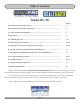
Table of Contents Model RC-50 A.) Important Safety Instructions.............................................................................. . Page(s) 4 B.) Identifying the RC-50 Components..................................................................... 5 C.) Tools and Materials Required.............................................................................. 6 D.) Site Survey........................................................................................................
A.) IMPORTANT SAFETY INSTRUCTIONS When installing and using this electrical equipment, basic safety precautions should always be followed, including the following: 1. READ AND FOLLOW ALL INSTRUCTIONS. 2. For Model: RC-50 WARNING - To reduce the risk of injury, do not permit children to use this product unless they are closely supervised at all times. 3.
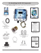
B.) Identifying the RC-50 Components The RC-50 MineralPURE unit should contain all the components listed below. Control Unit (1) Copper Test Kit (1) CLA-41 Users Manual (1) ScaleBlaster Signal Wire (60ft.
C.) Tools and Materials Required • Bullet Level • Channel Lock Wrench • Conduit Connector, ½” Straight • Conduit, Flexible/Electric hookup cable • Crescent Wrench • Drill & Drill Bits • Hacksaw or Pipe Cutter • Hammer • PVC Cement • PVC Cleaner/Primer • Screwdrivers, Flat & Phillips • Screws & Anchors • Teflon Tape or Liquid Teflon • Utility Knife • Voltage Meter • Wire Stripper • Other tools may be required D.
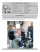
E.) Installing the Unit Installing the Electrode Chamber Turn off the pump and all valves. Disconnect all power going to the motor, timer box or power source. 1.) Wrap Teflon tape around the two threaded male adapters. You can also use “Liquid Teflon” a thread sealant with Teflon. Always use plenty of tape to avoid possible leaks. Screw adapters into the black flow cell chamber. 2.
E.) Installing the Unit (Continued) 6.) Seat the “O” ring in the electrode jar and hand tighten onto the black flow-cell chamber, no Teflon tape or wrench required! Choosing a power source The RC-50 unit will automatically detect 110 or 220VAC and no internal adjustments are required. When choosing a power source, choose a source that turns on and off with the pump motor. It is very important that the unit turn off when there is no water flowing past the electrodes. The ideal source is the timer box.
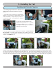
E.) Installing the Unit Mounting the Control Box (Continued) (continued) 2.) Install the four mounting brackets using the enclosed screws to the back of the control box. Mount the control box to the wall allowing for the electrode and coil wire to reach prospective locations. Remember the ScaleBlaster wire has to reach the area of the pipe where the coil will go and return back to the control box. Hold the control box up to the wall or surface to where it will be mounted and mark the four screw holes.
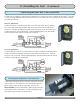
E.) Installing the Unit (Continued) Connecting the timer box to the control box 4) Below is an example of connecting the control box to a timer box. In this example an Intermatictm timer box is used. Although most timer boxes are similar they are not exactly the same, please take care when using the provided information. 230 VAC Operation: Connect the black (3 stranded) wire cable to the 230 VAC timer box by splicing the 3 wires and connecting the black and white wires to the LOAD side on the timer box.
E.) Installing the Unit (Continued) Connecting the control box to the electrical source 6.) A small flat head screw driver is required for installation. Once the wiring is run through the conduit, attach the wires to the terminal block located on the inner left side of control box. Attach the black wire to the terminal marked LINE, attach the white wire to the terminal marked NEUTRAL, and finally attach the green wire to the terminal marked GROUND. Refer to the wiring diagram located in this section.
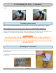
E.) Installing the Unit (Continued) Wrapping the pipe with the ScaleBlaster signal cable PVC, CPVC, or PEX PIPE INSTRUCTIONS 1.) Insert the pre-stripped end of the signal cable into one of the two signal terminals and tighten. 2.) Route the signal cable to the inlet pipe. Hold cable parallel and next to the pipe. 3.) Wrap one of the cable ties tightly so that the signal cable is secured to the pipe. (Figure A) 4.) Wrap the loose end of the signal cable securely around the pipe - in any one direction.
F.) Balancing the Pool’s Water Before turning on the system, it is imperative that the pool’s water be clear and balanced properly. Without proper balancing, the unit may not perform properly. Previous Sanitizer Use If the previous sanitizer used was Baquacil, you will need to remove every drop of it, as Baquacil is not compatible with any other sanitizer including MineralPURE. The best way to remove it is to drain the pool completely and refill with fresh water.
F.) Balancing the Pool’s Water (Continued) pH Reading Must be Between 7.2 and 7.8 The most important factor is in water chemistry is the pH reading. It should be kept between 7.2 and 7.8 at all times. If the pH gets too high, MineralPURE’s ions loose their effectiveness and can fall out of solution. Always get the pH on the lower side – 7.2 to 7.4 for best results. This is standard water chemistry. If the pH is above 7.
F.) Balancing the Pool’s Water (Continued) Copper Level Before installing the MineralPURE unit, the copper level should be tested. There may be readings of copper sulfate in the water from leached copper piping or from a copper based algaecide. Correct the problem by either locating the copper pipe (usually next to a water heater) and balancing the pH, or eliminating any algaecides completely. Shock the pool with an extra heavy dose of chlorine to get rid of the algaecides.
G) Starting Up the System (continued) THE DESIRED ION LEVEL IN THE POOL IS 0.2 – 0.3 There are a lot of factors that can effect the rate the MineralPURE will produce the ions (see section in Troubleshooting). In order to get the desired reading of 0.2 to 0.3 quickly, you will need to set the unit to its maximum current output (600mA). Turn the knob clockwise to reach this setting. Again, if you can’t reach 600, do not worry at this time. Eventually, the TDS level will rise as will your readout.
H.) Proper Procedures of Maintaining a Healthy Pool INCLUDED WITH THIS PACKAGE IS A “QUICK CHART” THAT GIVES YOU THE BASICS OF MAINTAINING A PROPER POOL. PLEASE REFER TO THAT SHEET WHENEVER POSSIBLE. IF YOU EVER HAVE ANY QUESTIONS, CONTACT YOUR DEALER OR CLEARWATER ENVIRO FOR ANY ASSISTANCE. • Keep the pH between 7.2 and 7.8 • Keep total alkalinity between 80-120ppm • Maintain Ion level between 0.2 and 0.3 ppm • Maintain normal pool maintenance – keep filter cleaned, empty baskets, etc.
I.) Cleaning and/or Replacing the Electrodes The only part of the MineralPURE Ionizer that will need maintenance or replacement is the electrodes. They should last about 1-5 years depending on your pool size, length of swimming season, water temperature and how well the water was balanced (ion level, pH, etc.). If the LCD display reads a warning to “Check Electrodes”, it may be time to clean or replace them.
J.) RC-50 Control Box Features The RC-50 control box has one LCD display screen and one control knob for easy to use simplicity.
J.) RC-50 Control Box Features (Continued) Output Current Indicator This value indicates the output current flowing through the electrodes. It is adjustable from zero (OFF) to six hundred milliamps (mA) , in five mA increments. Electrode Status Icon STEADY ON - NORMAL OPERATION The electrode icon on the upper right side of the main screen indicates the electrical polarity as well as its operational status. The pictures to the right show the electrode icon switching from one polarity to the other.
J.) RC-50 Control Box Features (Continued) Scrolling Status Messages The scrolling status message is located at the bottom of the main screen. Listed below are the messages and their meanings. 1). UNIT FUNCTIONING CORRECTLY: Lets the user know everything is OK and that the control unit is functioning. 2). CHECK ELECTRODE CONNECTIONS: A problem with the electrode connection has been detected.
J.) RC-50 Control Box Features (Continued) Diagnostic Screen (Continued) 1) Turn the output current knob until the output set value is 000 wait about two seconds and you will notice the electrode icon will switch polarities. 2) Next dial in 025, and wait 2 seconds 3) Next dial in 010, and wait 2 seconds The control unit’s LCD display should now show the main screen. The diagnostic screen monitors seven different operational values. Each value is described in detail below.
J.) RC-50 Control Box Features (Continued) LCD Contrast Adjust Screen (Continued) 2) Next dial in 035, and wait 2 seconds 3) Next dial in 020, and wait 2 seconds The display will now look like the picture to the right. The LCD display’s contrast can now be adjusted. Adjustments will make the display easier to read in different light levels. After nine seconds of inactivity on the control knob the RC-50 will return to the main screen.
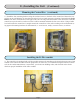
K.) Troubleshooting (Continued) Can’t Obtain the Proper Copper-Ion Level (Continued) 5.) Improper test kit readings. Make sure you follow the proper Ion-Test kit procedures. Many people look at the side of the test tubes instead of looking down from the top. Also, be sure to wait three minutes for the reagents to develop. These reagents should be replaced yearly and kept out of direct sunlight and stored at normal room temperature. Failure to do so will cause faulty readings.
K.) Troubleshooting (Continued) No Output Reading on Display / Unit Not Working Properly If for any reason you do not get a reading on the control box, and assuming all connections are correct, you will need to return the circuit board/face plate back to your dealer for repair. The circuit board/face plate assembly can be easily removed without having to un-install the enclosure or wiring. Always turn the power source off first! To Return the Circuit Board: 1.) Open clear door cover 2.
M.) RC-50 Specs RC-50 IONIZER SPECIFICATION SHEET Water Specifications POOL SIZE: up to 50,000 U.S. gallons IONIZATION METHOD: electrolysis of copper or copper/silver alloy electrodes ELECTRODE CHAMBER: 2” black tee with bushings for 2” or 1 ½” PVC pipe ELECTRODE: one set 3” long, comprised of copper (CLE-11) or optionally available copper/silver alloy (CLE-42 or CLE-44) HEAD LOSS: Flow Rate 25 gpm 50 gpm Total Head Loss (psi) 0.06 psi 0.
NOTES Page 27
The Healthy Alternative to Chlorine Manufactured by Phone: 727-562-5186 • Toll Free: 800-756-7946 • Fax: 727-562-5187 clearwater-enviro.com • MineralPURE.