! "# $ %&
WARNING THIS DOCUMENT CONTAINS MINELAB ELECTRONICS PTY LIMITED RIGHTS TECHNICAL DATA OR RESTRICTED RIGHTS DATA OR BOTH. Minelab Electronics This work is copyright.
TABLE OF CONTENTS 1. Introduction ................................................................................... 4 2. General Description and Preparation........................................... 6 2.1 Mine Detecting Set .................................................................... 6 2.2 F3 Main Components ................................................................ 8 2.3 F3 Preparation........................................................................... 9 2.
5.8 Completion of Operations ........................................................ 42 6. Care and Trouble Shooting......................................................... 43 6.1 Routine Care ........................................................................... 43 6.2 Trouble Shooting ..................................................................... 44 7. Specifications ..............................................................................
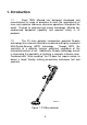
1. Introduction 1.1 Since 1996, Minelab has designed, developed and manufactured its range of detectors to meet the requirements of mine and explosive ordnance clearance operations throughout the world. Through its patented and unique technology, Minelab has emphasised equipment capability and operator safety in its products. 1.2 The F3 mine detector incorporates patented Bi-polar technology that enhances Minelab’s renowned and highly successful Multi-Period-Sensing (MPS) technology.
1.3 The F3 is a robust detector that is extremely simple to operate. There are no complicated controls resulting in the operator being able to focus on the vital task of mine detection. If mine detection occurs in a “difficult” environment that includes highly mineralised ground or electrical interference from over head power lines or other sources, simple and quick semi-automatic procedures can be initiated by an operator to allow the detector to continue performing at maximum capability. 1.
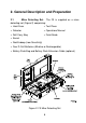
2. General Description and Preparation 2.1 Mine Detecting Set.
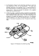
a. As illustrated in Figure 2, the Hard Case includes an insert for easy placement of the F3 and accessories. The case also provides protection for the detector and it is recommended that the F3 be secured in its Hard Case whenever it is not in use or during transit. Failure to transport the detector in the supplied Hard Case may void warranty. b. A Soft Carry Bag is supplied to allow an operator to comfortably carry the detector when use of the Hard Case is impractical (e.g.
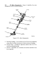
2.2 F3 Main Components. Figure 4 identifies the main components of the F3 which comprise: Armrest Strap Endcap Armrest Upper Shaft Electronics Pack Handle Battery Pack Middle Shaft Upper Camlock Lower Shaft Middle Camlock Coil Lower Camlock P0635-A Skidplate Figure 4: F3 – Main Components a. Sensitivity Endcap – the sensitivity of the F3 can be changed by using either the Black (maximum) or Red (minimum) Endcaps. b.
d. Electronics Pack – contains the electronics of the F3 and is permanently fixed to the detector. e. Upper Shaft – made of aluminium for increased robustness and provides mounting for the Handle, Battery Pack, Electronics Pack and Armrest. f. Battery Pack – removable to reduce the weight of the F3 for periods of prolonged use – contains four D cell batteries. g. Handle – ergonomically designed for operator comfort and includes Earset connector and F3 controls. h.
e. Unlock the Battery Pack Lid by twisting the Battery Lock Lever counter clockwise one-quarter turn. Once unlocked, pull the lid away from the Battery Pack (the lid will stay attached to the Battery Pack by a tether – Figure 5). Battery Pack Battery Lock Lever Battery Pack Lid Battery Map P0615-A Figure 5: Removing the Battery Pack Lid f. Using the battery maps, located on the side of the Battery Pack and on the inside of the Battery Pack Lid, insert four D cell batteries.
g. Extend the Lower and Middle Shafts to suit the selected demining position as shown in Figure 6. For use in the standing position: P0619-A P0618-A P0620-A Figure 6: F3 in the Standing, Kneeling or Prone Positions • Open the Lower Camlock and rotate the coil to the desired position. The normal operating position of the coil is in line with the shaft. However, the coil can also be positioned at right angles to either side of the shaft (required if the F3 is to be used in the prone position).
Middle Camlock Upper Camlock Lower Camlock P0617-A Figure 7: Camlock Locations • Holding the detector with the coil pointing toward the ground, open the Middle Camlock and extend the Lower Shaft to the desired length. Lock the Lower Shaft into position by closing the Middle Camlock. NOTE The Lower Shaft must be extended at least 100mm (4ins). Incorrect operation of the detector may result if the detector is used with the Lower Shaft fully retracted.
P0638-B Figure 8: Fitting the Earset NOTE The Earset connector is waterproof and it is most important that it is connected and disconnected from the Earset socket by holding the rubber collar. Do not attempt to connect or disconnect the Earset by pushing or pulling on the strain relief or wire at the rear of the rubber collar. i. For operator comfort, adjust the Armrest by opening the Armrest Camlock and then slide the Armrest to the desired position.
Upper Shaft Battery Pack Electronics Pack Lock Lever P0616-A Figure 9: Battery Pack Removal To refit the Battery Pack, ensure that the Lock Lever at the front of the Electronics Pack is in the unlocked position and position the Battery Pack on the rail underneath the Upper Shaft. Slowly slide the Battery Pack towards the Electronics Pack until the connector is firmly engaged. Secure the Battery Pack by rotating the Lock Lever in a clockwise motion into the locked position. 2.
2.5 Changing Endcaps. The F3 can be used with Black or Red Sensitivity Endcaps. The decision on which Endcap to use will be provided by the local authority. To fit a Sensitivity Endcap: a. Ensure the F3 is switched off. b. Place the thumb of one hand in the centre of the Endcap and curl the fingers under the base of the Endcap. c. Gently push inwards with the thumb and simultaneously pull the base of the Endcap away from the Electronics Pack (Figure 11). d.
3. Functional Description 3.1 Functional Controls. For ease of use, all controls for the F3 are located on the Handle. For information on the additional controls included in the F3L configuration, refer to Chapter 4. Figure 12 illustrates the location of all controls: Ground Balance/ Audio Reset Button Noise Cancel Button On/Off Switch Earset Socket P0621-A Figure 12: F3 Controls a. On/Off Switch. • The F3 is switched on by sliding the On/Off Switch toward the Handle.
• During operation, continuous internal self-testing continues and an alarm tone is triggered on detection of any fault condition (refer to Section 3.3 for a description of the alarm tones). • To turn the F3 off, slide the On/Off Switch away from the Handle. b. Ground Balance/Audio Reset Button. Easily identifiable as the Green Button located on top of the Handle, this dual action button carries out the following functions: • Ground Balance.
• A standard humanitarian demining Earset (Earset Speaker On) permits the F3’s internal speaker to continue to function even when the Earset is connected. • For military countermine applications, an Earset that mutes the F3’s internal speaker when the Earset is connected is available (Earset Speaker Off). The Earset Speaker Off is identified by a short length of green tubing located at the rear of the Earset plug.
Endcap is partially dislodged or removed during use, an alarm tone will sound. **WARNING** Where a minimum metal mine threat exists, the F3 MUST be operated with the Black Sensitivity Endcap. Depending on the size of the target and the depth of detection required, the Red Sensitivity Endcap may not be suitable for use. It is recommended that, prior to operational use, the capability of the F3, fitted with the Red Sensitivity Cap, be tested against the local threat to ensure detection occurs. 3.
depending on target metal composition and depth Low Battery Indicates batteries do not have enough charge to continue detection High pitched fast continuous oscillating tone Equipment Fault Indicates failure of detector component or a dislodged Red Sensitivity Endcap Low pitched slow oscillating tone (eeaww, ee-aww) Coil Fault Indicates coil not connected or not receiving sufficient current Low pitched double tone every five seconds Noise Cancel Indicates Noise Cancel procedure is occurring Two s
3.4 Test Piece – Functional Test. The F3 is supplied with a Test Piece specially designed to confirm that the detector is working to correct specifications. The sensitivity of the detector should be checked with the Test Piece before, during and after demining operations, (in compliance with local Standard Operating Procedures). In some instances, a user may prefer to use inert mines as test pieces because they represent the local threat.
4. F3L Configuration 4.1 Introduction. Detectors fitted with the LED Display and Volume/Sensitivity (V/S) Control leave the factory with the LED Display and Volume/Sensitivity Control enabled. The LEDs give an operator a visual indication of the size and proximity of a target. The V/S Control provides the facility to reduce or increase V/S levels to suit specific detection circumstances. If required, the LED display and the ability to vary V/S levels can be disabled on the F3L. 4.2 Description.
4.3 Operation-Volume/Sensitivity Control. From the default (middle) V/S setting, it is possible to increase or decrease V/S levels in five steps. Regardless of the V/S level selected, the volume of the Threshold Tone will remain the same. For safety reasons, the V/S setting will always commence at the default (middle) setting every time the F3L is switched on. The Test Piece Procedure must ALWAYS be carried out at the default V/S level setting.
• switching the F3L off and on. d. Disabling and Enabling Volume/Sensitivity Control. The F3L factory pre-set is V/S Control enabled but this feature can be disabled or enabled as follows: • Disable. To disable the V/S Control after the detector has been button and simultaneously, switched on, press and hold the quickly press and release the black Noise Cancel Button. If done correctly, a double tone will be heard. • Enable.
NOTE If more than one LED is illuminated or the display is erratic (in combination with a variable tone response), conduct Audio Reset and/or Noise Cancel.
a. Disabling and Enabling LED Display. The F3L factory pre-set is LED display enabled but this feature can be disabled or enabled as follows: • Disable. With the detector switched on, to disable the LED button and simultaneously, quickly display, press and hold the press and release the green Ground Balance button. NOTE Once the LED display is disabled, unless subsequently enabled, the LEDs will remain extinguished even if the detector is repeatedly switched off and on. • Enable.
5. Operating Procedures 5.1 Introduction. The F3 is designed to ensure that operation of the detector is as simple as possible. Additionally, the F3 is extremely capable, safe to use, robust and eliminates the need for complicated controls or lengthy training requirements. This Chapter describes procedures for safe and effective operation of the F3.
5.2 Standard Procedure. After unpacking the F3 and preparing it for use as described in Chapter 2 (appropriate Sensitivity Endcap fitted as directed by the local authority), complete the THREE step standard procedure as follows: Ground Balance/ Audio Reset Button Noise Cancel Button On/Off Switch Earset Socket P0621-A Figure 16: F3 Controls a. STEP 1 • Switch ON Hold the coil at least 600mm (24ins) from the ground and away from any metallic objects.
Start-Up Tones a low volume Threshold Tone will remain audible. Figure 18: Switch On • If the Threshold Tone is steady continue with STEP 2. If the Threshold Tone is noisy or uneven when the coil is stationary, perform a Noise Cancel (Section 5.3.a). • If the Threshold Tone is steady but seems louder than normal when the coil is away from the ground and metallic targets, perform an Audio Reset (Section 5.3.b). b.
Beep Beep 150mm (6 in) P0623-A Figure 19: Ground Balance Procedure NOTE Movement of the coil during the entire Ground Balance procedure should be slow, continuous and smooth and each down and up movement should take 3 to 4 seconds. If the Ground Balance OK tone is not heard within 30 seconds of starting the procedure, release the Ground Balance button and repeat this procedure. If there is metal in the ground under the coil whilst Ground Balancing, the detector will not Ground Balance correctly.
c. STEP 3 • Test Piece Ensure the operator’s hands and arms are free of metallic objects (watches, rings etc), and that no other metallic objects are near the coil. The orientation of the Test Piece during the test is dependent on which Sensitivity Endcap is connected to the detector. NOTE Maximum sensitivity is only available 30 seconds after the Threshold Tone commences. Do not test the detector with the Test Piece until 30 seconds after the Threshold Tone begins.
• Red Sensitivity Endcap: Hold the Test Piece above the middle of the coil with the rounded end (containing the metallic target) TOWARDS the coil. Move the Test Piece towards the centre of the coil until it lightly touches the surface then move it sideways off the coil (the Test Piece should be moved slowly and smoothly during this procedure). A clear response (change in Threshold Tone volume and pitch) should be heard indicating the sensitivity of the detector is correct.
P0649-A Figure 21: Noise cancel • Noise Cancel will commence with two single beeps followed by 45 seconds of sharp double beeps finishing with four single beeps. • During the 45 seconds, the detector scans the environment searching for any electrical interference. Once detected, the F3 will automatically select a different operating frequency to eliminate or reduce the interference. b. Audio Reset.
P0646-A Figure 22. Audio Reset NOTE If the Audio Reset button is held too long, the detector will commence the Ground Balance procedure. Noise Cancel and Audio Reset procedures can be performed at any time the Threshold Tone becomes noisy, uneven, or rises in volume. Once Noise Cancel or Audio Reset is complete, continue with steps 2 and 3. Figure 23 illustrates this sequence. Once completed, the F3 can commence operations in compliance with local Standard Operating Procedures.
STEP 1 SWITCH ON Optional Procedure Threshold Noisy/Uneven Y NOISE CANCEL N Threshold Louder than Normal Y AUDIO RESET N STEP 2 GROUND BALANCE STEP 3 TEST PIECE Figure 23: Standard & Optional Procedure 35
5.4 Sweeping Procedure. The F3 should be swept with a smooth even motion at a speed of 0.6 m/s (2 ft/s). If the detector is swept too fast or too slow, small or deep targets may be missed. The coil should always be kept at the same height above the ground with care taken to ensure that the coil is not inadvertently raised at the end of each sweep (Figure 24). Direction of Movement Mine Lane P0655-A P0624-A Figure 24: Sweeping Procedure a.
• confirm the target is not in close proximity to a second target thereby avoiding a possible booby trap. 5.5 Pin-Pointing Procedure. The design of the F3 makes pinpointing accurate and fast. The F3’s monoloop coil means there are no gaps in sensitivity around the coil’s circumference or across its surface. Pin-Pointing is conducted as follows: a.
**WARNING** Extreme care must be taken when mapping the target to ensure that the coil does not touch the ground (or any exposed parts of the mine) or snag on any previously undetected trip wires. For large minimum metal anti-tank mines, it is possible that the area mapped out may be less than the actual area of the mine. After an initial detection, if the coil is repeatedly swept over a small deeply buried target, the response may fade.
Maximum Volume Figure 26: Determining Target Centre NOTE An operator can confirm that the centre of a target has been located by moving the coil slightly, in any direction, and returning to the centre. In doing so the volume of the Threshold Tone should decrease from maximum as the coil leaves the centre and return to maximum as the coil returns to the centre. 5.6 Multiple Targets. There may be occasions when an operator will encounter multiple targets.
P0627-A Figure 27: Mapping Multiple Targets NOTE To an experienced operator the shape of the mapped area can indicate whether multiple targets may be present. b. STEP 2 Determining the Centre of Target • The pitch of the Threshold Tone will rise or fall depending on the combination of metals or the composition of metal in a mine. This means that, in some instances, experienced operators may be able to identify one mine against another (Figure 28).
+ Figure 28: Multiple Targets 5.7 Operating Multiple Detectors in Close Proximity. On occasion it may be necessary to operate F3 detectors in close proximity. In normal circumstances, an F3 detector can operate as close as 2 metres (7 feet) to another F3 detector without suffering excessive mutual interference. To achieve this minimum operating distance between detectors, Noise Cancel is to be conducted as follows: a.
NOISE CANCEL 2 metres Figure 29: Operating Detectors in Close Proximity 5.8 Completion of Operations. At the completion of operations, the F3 should be checked with the Test Piece before switching off to ensure satisfactory performance before being packed away. Once completed: a. Turn the detector off. b. Clean the detector and inspect for any signs of damage (Chapter 6). c. Remove the batteries from the Battery Pack and stow in the Hard Case or Soft Carry Bag. d. Disconnect the Earset. e.
6. Care and Trouble Shooting 6.1 Routine Care. The F3 is designed for lasting use in harsh operating environments. However, proper care and maintenance will ensure long-term reliability. Key to ensuring the survivability of the F3 is the correct stowage of the detector into its Hard Case whenever the detector is not in use. Additionally, operators of F3 detectors should be aware of the following: a. During rest periods, wherever possible, the detector should be sheltered from direct sun, rain, snow etc. b.
6.2 Trouble Shooting. The following table provides several trouble shooting procedures in response to a variety of possible problems: Problem Recommended Procedure F3 will not switch On 1. Check batteries have been inserted correctly into the Battery Pack - or 2. Replace batteries - or 3. Remove Battery Pack and reconnect ensuring battery Lock Lever is locked into position - or 4.
Cannot hear the Test Piece with the Red Sensitivity End Cap 1.
7. Specifications Length: Operating Length 1500mm/59.4ins to 750mm/30ins Weight: Operating weight with batteries (complete) 3.2kg/7lbs Operating weight without Battery Pack 2.3kg/5lbs Battery Pack with batteries 0.9kg/2lbs Shipping weight (in hard case with batteries) 10.
Environmental: Temperature (Operating) -30 deg C to 60 deg C -22 deg F to 140 deg F Temperature (Storage) -30 deg C to 80 deg C -22deg F to 176 deg F Environmental Resistance To MIL STD 810F: Method 512.4 (Water immersion IP67) Method 514.5 (Vibration) Method 516.
Contact Details: Minelab Electronics Pty Ltd PO Box 537 Torrensville Plaza South Australia 5031 AUSTRALIA email: countermine@minelab.com.au tel: +61 88238 0888 Minelab USA 871 Grier Drive, Suite B-1 Las Vegas, Nevada 89119 UNITED STATES OF AMERICA email: countermine@minelab.com.au tel: +1 702 891 8809 Minelab International Limited Laragh, Bandon Co. Cork IRELAND email: countermine@minelab.com.au tel: +353 23 52101 www.minelab.