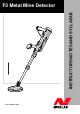
INSTRUCTORS NOTES AND SYLLABUS F3 Metal Mine Detector Issue 1.
F3 INSTRUCTOR NOTES WARNING THIS DOCUMENT CONTAINS MINELAB ELECTRONICS LIMITED RIGHTS TECHNICAL DATA OR RESTRICTED RIGHTS DATA OR BOTH. Minelab Electronics This work is copyright. Apart from any use as permitted under the Copyright Act 1968, no part may be reproduced by any process without written permission from Minelab Electronics 118 Hayward Avenue, Torrensville South Australia.
SLIDE F3 INSTRUCTOR NOTES DESCRIPTION INSTRUCTORS NOTES These Instructor Notes are produced to assist instructors in preparing for the F3 Operator Training Course. They are provided as a guide and are not intended to be prescriptive. They should be used in combination with the information contained in the F3 Operations Manual and Field Guide. The confirmation of a student’s ability to operate the F3 will be achieved through a series of performance objectives completed after each lesson.
Three F3 INSTRUCTOR NOTES LESSON 1 – GENERAL DESCRIPTION & PREPARATION Aim. Correctly describe and identify the F3 and prepare it for use. Classroom Instruction.
Five F3 INSTRUCTOR NOTES Mine Detecting Set Using the F3 in the Hard Case identify the following components: • Hard Case • Detector with Black Endcap • Soft Carry Bag • Earset (with Volume Control) • Red Low Sensitivity Endcap • Four D Cell Batteries • Test Piece • Operations Manual • Field Guide • Six Soft Carry Bag Show the F3 in the Soft Carry Bag and locate the following: • Detector with Black Endcap • Red Low Sensitivity Endcap • Earset (with Volume Control) • Four D Cell Batteries • Operations
F3 INSTRUCTOR NOTES if the client has purchased the option of a Battery Charger then four NiCad ‘D’ cell batteries will have been provided. The Battery Pack can be removed to reduce weight for periods of prolonged use provided the optional Battery Pack Bag & Extension Cable is included with the detector. o Upper, Middle and Lower Shafts. Identify Upper Shaft: • Made of aluminum for robustness. • Provides mounting for handle, Electronics Pack and Armrest.
Eight F3 INSTRUCTOR NOTES F3 Preparation To prepare the F3 for operations the following procedure should be followed: • Open the Hard Case or Soft Carry Bag. • Remove the F3 and inspect for obvious signs of damage. • Check that the correct Sensitivity Endcap is selected and mounted correctly. (Changing Endcaps discussed in Slide 10).
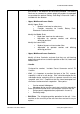
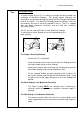
F3 INSTRUCTOR NOTES Upper Shaft Battery Pack Electronics Pack Lock Lever P0616-A o Slowly slide the Battery Pack towards the Electronics Pack until the connector is firmly engaged. Secure the Battery Pack by rotating the Lock Lever in a clockwise motion into the locked position. o If required, the Battery Pack can be separated from the Upper Shaft thereby reducing the overall weight of the detector.
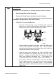
F3 INSTRUCTOR NOTES either side of the shaft (required if the F3 is to be used in the prone position). Once the position of the coil is selected, lock it into position by closing the Lower Camlock. P0618-A P0619-A P0620-A o In sequence, extend the Lower and then Middle Shafts to suit the deminer’s height and selected demining position. NOTE The Lower Shaft must be extended at least 100mm (4ins).
Ten F3 INSTRUCTOR NOTES Changing Endcaps • A unique feature of the F3 is its ability to change sensitivity through the exchange of Sensitivity Endcaps. This design feature eliminates the possibility of an operator selecting the wrong sensitivity through manipulation of dials or switches. The Sensitivity Endcap provides an obvious visual cue that confirms the level of sensitivity selected in the F3.
F3 INSTRUCTOR NOTES NOTE If the Red Sensitivity Endcap is not fitted correctly, or there is no endcap fitted, the detector automatically defaults to the maximum sensitivity setting (Black Sensitivity Endcap). If the Red Sensitivity Endcap is partially dislodged or removed during use, an alarm tone will sound. **WARNING** The Sensitivity Endcap also provides impact protection to the Electronics Pack.
Eleven F3 INSTRUCTOR NOTES LESSON 2 – FUNCTIONAL DESCRIPTION Aim. Correctly identify and describe the functional controls and tones and the F3. Classroom instruction.
F3 INSTRUCTOR NOTES o These internal diagnostics take approximately 12 seconds to complete during which the operator will hear a series of rising tones (known as the Start-Up Tones). o At the completion of the Start-Up Tones the F3 emits a low steady tone known as the Threshold Tone, which confirms to the operator that the F3 is functioning correctly.
F3 INSTRUCTOR NOTES permits the F3’s internal speaker to continue to function even when the Earset is connected. o For military countermine applications, an Earset that mutes the F3’s internal speaker when the Earset is connected is available (Earset Speaker Off). The Earset Speaker Off is identified by a short length of green tubing located at the rear of the Earset plug. o A further option includes a volume control located on the cable between the Earset plug and earpiece.
Fourteen F3 INSTRUCTOR NOTES Functional Tones Tones Equipment Fault Coil Fault Noise Cancel Event Indicates failure of detector component or a dislodged Red Sensitivity Endcap Indicates coil not connected or not receiving sufficient current Indicates Noise Cancel procedure is occurring Description Low pitched slow oscillating tone (ee-aww, ee-aww) Low pitched double tone every five seconds Two single beeps followed by 45 seconds of short double beeps finishing with four single beeps NOTE Circuitr
Fifteen F3 INSTRUCTOR NOTES LESSON 3 – OPERATING PROCEDURES Aim. To correctly perform F3 operating procedures. Classroom instruction.
F3 INSTRUCTOR NOTES P0645-A The F3 will emit a series of four rising tones over 12 seconds (internal diagnostic checks occurring). At the completion of the Start-Up Tones listen for the low volume Threshold Tone. This slide includes embedded wav file to demonstrate applicable tones. If the Threshold Tone is steady continue with STEP 2. If the Threshold Tone is noisy or uneven when the coil is stationary, perform a Noise Cancel.
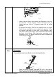
F3 INSTRUCTOR NOTES Beep Beep 150mm (6 in) P0623-A NOTE Movement of the coil during the entire Ground Balance procedure should be slow, continuous and smooth and each down and up movement should take 3 to 4 seconds. If the Ground Balance OK tone is not heard within 20 seconds of starting the procedure, release the Ground Balance button and repeat this procedure. If there is metal in the ground under the coil whilst Ground Balancing, the detector may not ground balance correctly.
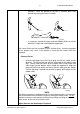
F3 INSTRUCTOR NOTES P0647-A Red Sensitivity Endcap: Hold the Test Piece above the middle of the Coil with the rounded end (containing the metallic target) TOWARDS the coil. Move the Test Piece towards the centre of the Coil until it lightly touches the coil then move it sideways off the Coil (the Test Piece should be moved slowly and smoothly during this procedure). A clear response (change in Threshold Tone volume and pitch) should be heard indicating the sensitivity of the detector is correct.
F3 INSTRUCTOR NOTES P0649-A Noise Cancel will commence with two single beeps followed by 45 seconds of sharp double beeps finishing with four single beeps. (Embedded wav file in slide) During the 45 seconds, the detector scans the environment searching for the source of any electrical interference. Once detected, the F3 will automatically select a different operating frequency to eliminate or reduce the interference. o Audio Reset.
F3 INSTRUCTOR NOTES Procedures. NOTE Noise Cancel and Audio Reset procedures can be performed at any time the Threshold Tone becomes noisy, uneven, or rises in volume. Having completed STEPS 1, 2 and 3 the F3 remembers the Ground Balance setting even after the detector has been switched off. After Noise Cancel is completed the F3 remembers the frequency selected to minimize interference, even if the detector is switched off. Eighteen Summary of Procedures Explain the following summary of procedures.
F3 INSTRUCTOR NOTES o The detector remembers its Ground Balance condition after being switched off and will retain it until another Ground Balance is conducted. The detector remembers its Noise Cancel condition after being switched off and will retain it until another Noise Cancel is conducted.
Nineteen F3 INSTRUCTOR NOTES Sweeping Procedure • The F3 should be swept with a smooth even motion at a speed of 0.6 m/s (2 ft/s). If the detector is swept too fast or too slow, small or deep targets may be missed.
F3 INSTRUCTOR NOTES Edge Detection makes use of the coil’s consistent sensitivity around its circumference to detect the edges of a target. To conduct edge detection, the coil should approach the suspected location of the target from a variety of angles. As the coil approaches the target, the Threshold Tone will change indicating that the coil is in close proximity to the target.
Twenty One F3 INSTRUCTOR NOTES Pin-Pointing Procedure (Cont.) o STEP 2 Determine Centre of Target In Step 1, the area of a target was determined. If the metal in the target is sufficiently small, the area mapped will also be small and therefore it is a relatively simple matter to pin-point the centre of the target. For larger targets, to determine the centre, the coil should be slowly moved across the mapped area.
F3 INSTRUCTOR NOTES P0627-A NOTE To an experienced operator the shape of the mapped area can indicate whether multiple targets may be present. However, the volume from the large target may mask the volume of the smaller target and so great care is necessary for accuracy. If the coil is moved very close to the ground, it will be easier to hear a smaller target when close to a larger target. Twenty Three Multiple Targets (Cont.
Twenty Four F3 INSTRUCTOR NOTES Detectors in Close Proximity • On occasion it may be necessary to operate F3 detectors in close proximity. In normal circumstances, an F3 detector can operate as close as 2 meters (7 feet) to another F3 detector without suffering excessive mutual interference. To achieve this minimum operating distance between detectors, Noise Cancel is to be conducted as follows: o With all other detectors switched off, switch on the first detector and perform Noise Cancel.
F3 INSTRUCTOR NOTES Case or Soft Carry Bag. o Stow the detector in the Hard Case or Soft Carry Bag. o Ensure all components are correctly packed (especially the Test Piece and Earset).
Twenty Six F3 INSTRUCTOR NOTES LESSON 4 – Care & Trouble Shooting Aim. To ensure that students understand how to properly maintain and trouble shoot on the F3. Classroom instruction.
F3 INSTRUCTOR NOTES o Ensure batteries are removed before packing The Skidplate is designed to protect the Coil and may require replacement after long periods of use. To replace the Skidplate: o Use fingers to lever old Skidplate from coil o Apply even firm pressure around replacement Skidplate and push onto Coil P0654-A Twenty Eight F3 Trouble Shooting There are a number of actions that an operator can carry out when trying to fix a possible fault.
Twenty Nine F3 INSTRUCTOR NOTES Trouble shooting continued: Problem There is no sound from the Earset There is no sound from the Speaker Cannot hear the Test Piece with the Red Endcap Cannot hear the Test Piece with the Black Endcap Recommended Procedure 1. Disconnect and reconnect the Earset, or 2. Try a known serviceable Earset (if this solves the problem, the original Earset may be faulty) 1. Switch Off and On, or 2. Disconnect Earset, switch Off then On 1.
F3 INSTRUCTOR NOTES OUTDOOR TRAINING/DEMONSTARTIONS At the completion of the classroom instruction it is important that all students have a sufficient amount of time to become proficient in the operation of the F3. It is recommended that outdoor training be conducted over two full days. It is recommended that the outdoor training be conducted in purpose prepared training lanes and that there be enough lanes for two students per lane.
F3 INSTRUCTOR NOTES Once completed, the student should be able to indicate the centre of the target, or where there are several targets close together, the student should be able to outline an area that is considered dangerous. • Two targets resolution. The aim here is to show how to map two targets laid within close proximity to each other showing the actual shape on the ground of the dual targets.
F3 INSTRUCTOR NOTES An example of an Operator Confirmation Exercise Sheet is included at the end of these Instructor Notes. Equipment Cleared evaluation area – constructed as one mine lane (1m wide and 5m long) Targets to bury in the test area as described below – if inert mines are not available, F3 test pieces buried at varying depths will suffice WARNING If inert mines are to be used for the evaluation, ensure each mine is certified as free from explosive (FFE).
F3 INSTRUCTOR NOTES A suggested training lane layout is as follows: E D C B A START POINT • A - medium Size Target (PMA-2 det). demonstrate solid pinpointing technique. • B - large and Small Target (M14 and PMA-2). A student must demonstrate that they can actually detect two targets. Be careful to ensure that the students do not miss the smaller target by only recognizing a response from the larger target. The targets must be laid so that the small target can be heard.
F3 INSTRUCTOR NOTES forget the upper third one. A good operator will actually be able to state that there are three targets. Although identification of three targets is useful, if an operator cannot identify three separate targets, it is sufficient to outline the “danger” area during the mapping technique. • D - one large target right on the edge of the lane. To prove that not all mines are conveniently located in the middle of lanes. • E - one small target (single test piece).