WARNING THIS DOCUMENT CONTAINS MINELAB ELECTRONICS PTY LIMITED RIGHTS TECHNICAL DATA OR RESTRICTED RIGHTS DATA OR BOTH. Minelab Electronics This work is copyright. Apart from any use as permitted under the Copyright Act 1968, no part may be reproduced by any process without written permission from Minelab Electronics Pty Ltd 118 Hayward Avenue, Torrensville, SA 5031 Australia PDF created with FinePrint pdfFactory trial version http://www.fineprint.
PDF created with FinePrint pdfFactory trial version http://www.fineprint.
Operations Manual LIST OF CONTENTS 1. Introduction ................................ ................................ .................. 5 2. Specification................................ ................................ ................. 6 3. List of Parts ................................ ................................ .................. 9 4. Unpacking and Assembly ................................ ............................ 11 4.1 Shaft Assembly ................................ ........................
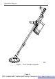
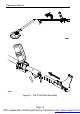
Operations Manual Figure 1 - The F1A4 Mine Detector Page 4 PDF created with FinePrint pdfFactory trial version http://www.fineprint.
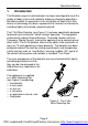
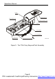
Operations Manual 1. Introduction The Minelab range of metal detectors has been developed to meet the needs of today“s mine and explosive ordnance clearance operations. Minelab has built its experience in the minefields of South East Asia, where its technology has been exposed to the harshest environments, including highly mineralised, magnetic ground. The F1A4 Mine Detector (see Figure 1) has been specifically designed to provide semi-automatic ”switch and go— operation.
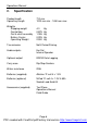
Operations Manual 2. Specification Packed length Operating Length 710 mm 1200 mm min - 1450 mm max. Weights Shipping weight Control box Coil & shaft assembly Battery Carrier Operating Weight 4.0 0.875 1.326 0.225 2.900 Transmission Multi Period Pulsing Audio outputs Ear Set Internal Speaker Optional output RS232 Data Logging Carry case Rip Stop Cordura Water resistance IP65 Batteries (supplied) Alkaline –D“ cell 4 x 1.5V Batteries (optional) NiCad –D“ cell 4 x 1.2V 4.
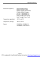
Operations Manual Accessories (optional) Rechargeable Batteries Battery Charger 6V SLA Battery Charger (Commercial) F Series Battery Charger Ear Set °Loudspeaker Off Ear Set °Loudspeaker On Hard Transport Case (6 unit) Hard Transport Case (1 unit) Temperature (operating) -30oC to +60oC Temperature (storage) -55oC to +90oC Patents US4890064, US4894618 AUS595835, CAN1260146 Page 7 PDF created with FinePrint pdfFactory trial version http://www.fineprint.
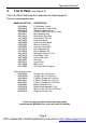
Operations Manual EARSET FIELD GUIDE F1A4 BAG CONTROL BOX OPERATIONS MANUAL F1A4 ARMREST BAG COMPACT 'D' CELL BATTERIES (4) CONTROL BOX TEST PIECE MINE DETECTOR P0141-C Figure 3 - The F1A4 Carry Bag and Parts Assembly Page 8 PDF created with FinePrint pdfFactory trial version http://www.fineprint.
Operations Manual 3.
Operations Manual Figure 4 - The F1A4 Shaft Assembly Page 10 PDF created with FinePrint pdfFactory trial version http://www.fineprint.
Operations Manual 4. a. b. c. Unpacking and Assembly Open the shipping container and remove the carry bag. Open the carry bag and check all standard and optional components are present and undamaged. Remove the components and assemble the detector in the following sequence. 4.1 Shaft Assembly (see Figure 4) a. b. c. d. e. Remove the armrest from the carry bag. Remove the main shaft (including handle) and lower shaft (including coil) from the carry bag.
Operations Manual Figure 5 - Control Box Configurations Page 12 PDF created with FinePrint pdfFactory trial version http://www.fineprint.
Operations Manual 4.2 Control Box (see Figure 5) The Control Box can be positioned in one of three locations: • it can be placed in its control box bag which is attached to the operator“s waist via two belt loops; • when the webbing strap is used, the control box bag can be worn over the operator“s shoulder, or it can hang around the operator“s neck; or • it can be attached to the main shaft via a locking bracket located beneath the handle. a.
Operations Manual Figure 6 - Armrest Configurations Page 14 PDF created with FinePrint pdfFactory trial version http://www.fineprint.
Operations Manual 4.3 Armrest (see Figure 6) To assemble the armrest: a. Insert the sharp end of the arm strap through one of the slots at the base of the armrest, then through the slots at the top of the wings of the armrest. When the operator“s arm is in the armrest, the protruding part of the –Velcro“ strap should be fixed to make a firm fit. b.
Operations Manual 'D' Cell Battery Carrier and Cover Battery Cover Remove Battery Cover Snaplocks Control Box Snaplocks Lead-Acid Battery Pack (Optional) Battery Cover Battery Cover Snaplocks Control Box Snaplocks P0019-D Figure 7 - The F1A4 Battery Pack Page 16 PDF created with FinePrint pdfFactory trial version http://www.fineprint.
Operations Manual 4.4 Battery Pack (see Figure 7) The F1A4 can be powered by one of two battery packs. NOTE: Before connecting or disconnecting either battery pack ensure that the unit is switched Off on the Control Panel. 4.4.1 Lead-Acid Battery Pack To use the belt-mounted Lead-Acid battery pack as a power source: a. It is necessary to undo the –snaplocks“ on the base of the Control Box and remove the Battery Carrier and Cover. b.
Operations Manual 4.5 Comfort Adjustments (see Figure 8) a. Releasing the upper camlock lever at the top end of the main shaft permits up to 50 mm adjustment of the position of the armrest assembly, relative to the handle position. b. Releasing the handle camlock lever at the base of the handle allows the handgrip to be repositioned along the length of the main shaft. c. Releasing the lower camlock lever at the bottom end of the main shaft enables the effective length of the lower shaft to be altered. d.
Operations Manual 5. Operating Instructions 5.1 Control Panel Description (see Figure 9) All controls are located on the Control Panel. Battery Low Noise Cancel MINELAB Off On Search Balance F1A4 Audio Reset Coil P0024-D Figure 9 - The F1A4 Control Panel 5.1.1 Off / Search / Balance Switch This three-position switch located near the centre of the Control Panel provides the ability to switch the unit On and Off. Normal detection operations are performed whilst in the Search position.
Operations Manual 5.1.2 Noise Cancel Noise Cancel negates the effects of electro-magnetic interference. Installations such as local television stations, radar transmitters and electrical power cables emit signals that can interfere with the detector. Performing a Noise Cancel procedure forces the detector to reset itself so as to minimise the effects of any interference.
Operations Manual 5.2 Detector Settings WARNING Operators should be aware of other electronic equipment being used in the immediate locality that may affect the operation of the detector. To initialise the detector in a new area, switch the detector from Off to Search. The detector takes 6 seconds to run through a set-up routine, and during this time 3 long –beeps“ with a slowly rising pitch can be heard.
Operations Manual 5.2.2 Noise Cancel Procedure When the detector gives a repetitive warble without the coil being moved, perform the following electromagnetic Noise Cancel procedure: CAUTION Keep the detector very still; do not handle the detector during this procedure. It can take some time and any movement can upset the process, as will any metallic objects being moved in the vicinity of the coil. Also ensure that there are no metallic objects near the coil during this procedure. a.
Operations Manual 5.2.3 Ground Balance Procedure (see Figure 10) Ensure that the Noise Cancel and Audio Reset procedures have been performed and then select an area known to be free of metallic particles. a. Place the detector with the coil resting on the ground. b. Turn the On/Off switch to Balance and hold the switch in this position. c. Move the coil slowly up and down from 25 to 100 mm above the ground. Each complete up and down movement should take 3 to 4 seconds.
Operations Manual 5.3 Detector Sounds WARNING The threshold tone is a safety tone and must be present to ensure correct operation of the detector. If there is a persistent change in this tone, the detector should be tested with the test piece before further use of the detector. (see Section 5.4 for further information on testing the detector.) a. Threshold Tone - is the background tone produced by the detector. The loudness of the threshold is set by the in-built microprocessor.
Operations Manual c. Ground Noise - is an irregular broad noise that is difficult or impossible to pinpoint when moving the coil over the ground. d. If ground noise is affecting the operator“s performance, rebalance the detector as described in the Ground Balance procedure. 5.4 Testing Procedure / Using the Test Piece The F1A4 test piece is used to ensure that when the following test is performed, operators can have full confidence that the detector is working to its optimum performance.
Operations Manual CAUTION Follow established standing operating procedures at all times, and use the supplied test piece to confirm that the detector registers a correct signal before and after every use. An area that has just been checked with the F1A4 detector should not be considered safe until the detector has been rechecked with the test piece. a. Ensure that the detector is emitting the correct threshold tone. If in doubt, perform Noise Cancel or Audio Reset procedure. b.
Operations Manual 5.5 Sweeping the Coil a. While sweeping the coil it is important to keep it parallel to and at a constant height from the ground at all times (see Figure 13). CAUTION Be aware of any tendency to raise the coil at the ends of each sweep as this will reduce your detection depth. b. Each sweep of the coil should overlap the area covered by the previous sweep to ensure full coverage of the area being searched. Figure 13 - Sweeping the Coil 5.
Operations Manual c. Advance forward another sweep distance and approach the coil from each side. Notice when the target signal is first heard ‘ this will indicate the side boundaries of the target area. (See Figure 14.) Figure 14 - Pinpointing a Small Target using Edge Detection 5.7 Pinpointing Large or Multiple Targets If you have a large target or multiple targets it may be difficult to define using the crossing method defined in section 5.6.
Operations Manual Figure 16 °Determining the Outline of the Target d. Note if the pitch rises or falls at each interval around the target. If the pitch sound is different it may indicate multiple targets, such as AP Mines or booby traps (see Figure 17). Figure 17 °Checking the Pitch around the target Page 29 PDF created with FinePrint pdfFactory trial version http://www.fineprint.
Operations Manual 5.8 Operating Multiple Detectors in Close Proximity When two or more F1A4 detectors are operating in close proximity it is necessary to automatically tune each unit via the Noise Cancel procedure to set the operating frequencies so that the F1A4 detectors do not interfere with each other. To set up multiple detectors it is necessary to adhere to the following procedure: a. Turn –Detector 1“ On, and switch to Search. Wait for the end of the start-up tone.
Operations Manual 6. Care of the F1A4 Detector The F1A4 Detector is a high quality electronic instrument that is finely engineered and housed in a durable container. Proper care and maintenance will ensure long-term reliability of the detector. Please observe the following precautions: • It is important to keep the connectors clean and dry when not in use. • The operating temperature range is between °30 C and +60 C. Storage temperatures should be kept between °55 C and +90 C.
Operations Manual 6.1 Operator Repairs 6.1.1 Replacing the Nylon Bolt, Nylon Nut or Friction Washers on the Coil (See Figure 19) Remove the Nylon (Wing) Nut and pull the Nylon Bolt from the assembly. Pull the Lower Shaft from the coil assembly, only enough to allow removal of the Friction Washers. To replace the Friction Washers, align the four locating pins with the locating holes and press the washer into position. Engage the Lower Shaft assembly over the Friction Washers and align the bolt hole.
Operations Manual 6.1.4 Replacing the Handgrip (See Figure 21) To remove the old Handgrip, unthread the Hand Strap and remove the Strap Jammer. Cut the old foam down the length of the handle and remove all foam residue. Wet the inside of the replacement foam and handle moulding with water, and slide the foam over the moulding. Refit the Strap Jammer in the Handle Moulding and rethread the Handle Strap. 7.
SKID PLATE DUST-CAP NYLON BOLT, BLACK FRICTION WASHER Figure 19 - F1A4 COIL ASSEMBLY PARTS COIL 200mm F1A4 FRICTION WASHER NYLON NUT, WING BLACK LOWER SHAF Operations Manual PDF created with FinePrint pdfFactory trial version http://www.fineprint.
Figure 20 - F1A4 CONTROL BOX ASSEMBLY PARTS DUST CAP DUST CAP BATTERY COVER CONTROL BOX Operations Manual Page 35 PDF created with FinePrint pdfFactory trial version http://www.fineprint.
LOCKPIN CONTROL BOX STRAP ASSEMBLY THREAD HANDSTRAP THROUGH HANDLE WITH JAMMER IN PLACE SERVICE KIT, CAMLOCK HANDLE HANDLE MOULDING Figure 21 - F1A4 HANDLE ASSEMBLY PARTS STRAP JAMMER HAND STRAP HANDGRIP FOAM Operations Manual PDF created with FinePrint pdfFactory trial version http://www.fineprint.
MAIN SHAFT F1A4 Figure 22 - F1A4 SHAFT ASSEMBLY PARTS SERVICE KIT, CAMLOCK LOWER SEE FIGURE 21 ARMSTRAP PATH P0085-C SERVICE KIT, CAMLOCK UPPER ARMREST ARMSTRAP Operations Manual PDF created with FinePrint pdfFactory trial version http://www.fineprint.
TEST PIECE MINE DETECTOR Figure 23 - F1A4 PACKING PARTS CONTROL BOX BAG CONTROL BOX EARSET 'D' CELL BATTERIES (4) OPERATI FIELD G Operations Manual PDF created with FinePrint pdfFactory trial version http://www.fineprint.
Operations Manual INTENTIONALLY LEFT BLANK Page 39 PDF created with FinePrint pdfFactory trial version http://www.fineprint.
Operations Manual INTENTIONALLY LEFT BLANK Page 40 PDF created with FinePrint pdfFactory trial version http://www.fineprint.