
User's Manual


Lead Placement Lead Placement
4 - 10 0070-00-0575-50 Panorama™ Operating Instructions
4.4.3 Special Considerations
Lead II Monitoring
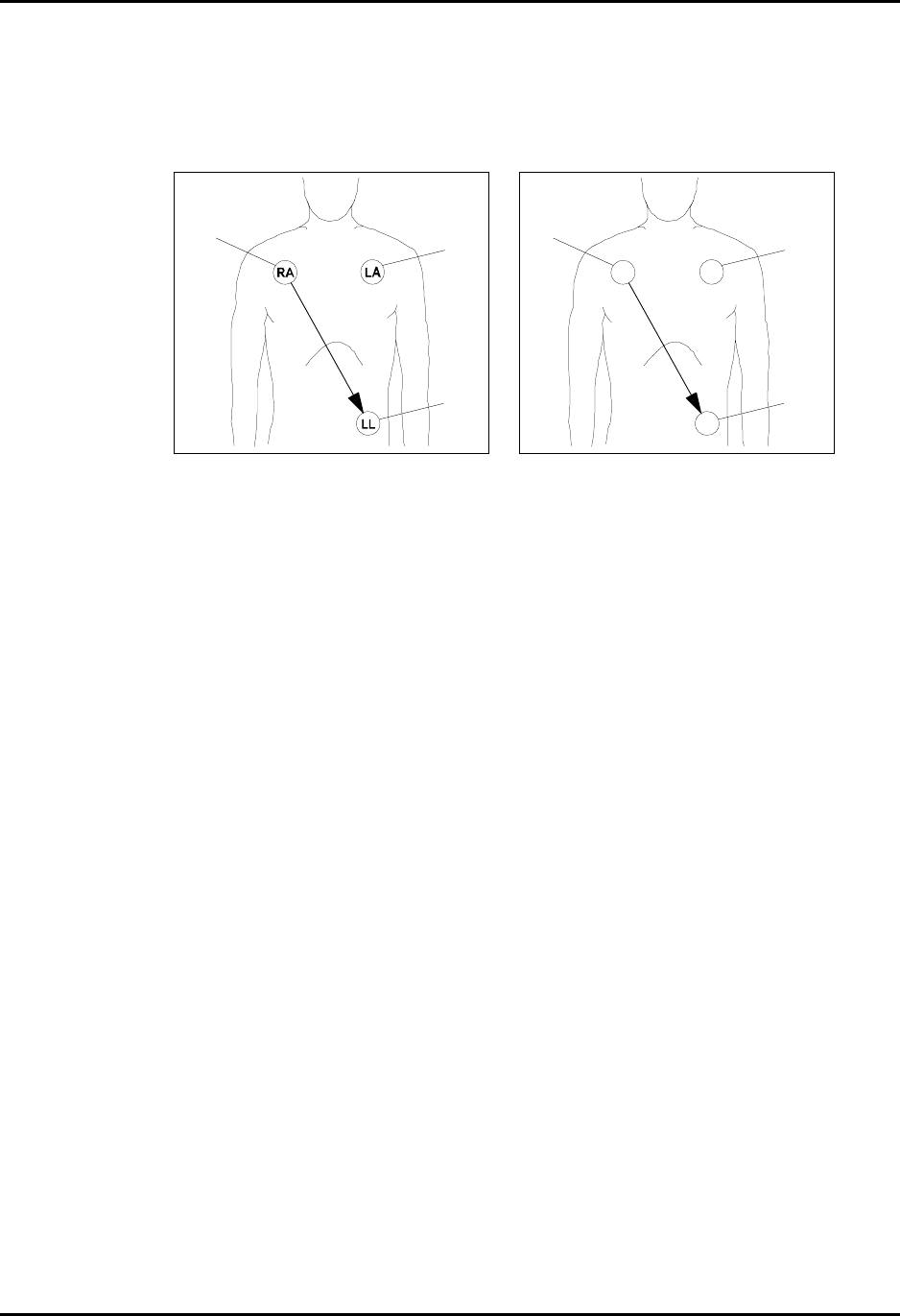
FIGURE 4-7 Lead II Monitoring (AHA) FIGURE 4-8 Lead II Monitoring (IEC)
• Place RA (white) electrode under patient
right clavicle, mid-clavicular line within the
rib cage frame.
• Place LA (black) electrode under patient
left clavicle, mid-clavicular line within the
rib cage frame.
• Place LL (red) electrode on the patient’s
lower left abdomen within the rib cage
frame.
• Select ECG Lead II on monitor. Lead II is
the direct electrical line between the RA
(white) electrode and the LL (red)
electrode.
• Place R (red) electrode under patient right
clavicle, mid-clavicular line within the rib
cage frame.
• Place L (yellow) electrode under patient left
clavicle, mid-clavicular line within the rib
cage frame.
• Place F (green) electrode on the patient’s
lower left abdomen within the rib cage
frame.
• Select ECG Lead II on monitor. Lead II is
the direct electrical line between the R
(red) electrode and the F (green) electrode.
White
Black
Red
Red
Ye ll o w
Green
R
L
F