
User's Manual


Display Tab Patient Setup Functions
5 - 32 0070-00-0575-50 Panorama™ Operating Instructions
• Always occupies the first digital data tile
• Displays an ECG lead label for the lead acquiring the data
• Displays an icon if Arrhythmia Analysis is enabled
• Displays an icon if ST Analysis is enabled
• Displays the standby location for a patient in Standby mode
Waveform Parameter Data
The patient tile is capable of showing up to two waveforms for a patient.
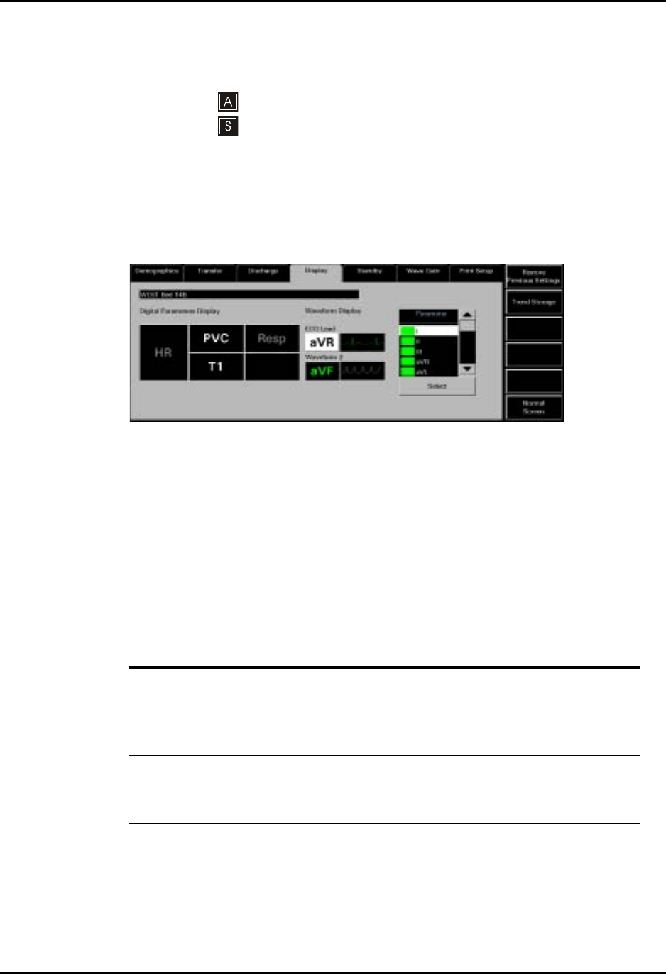
FIGURE 5-21 shows an example of the Display tab (waveform data).
FIGURE 5-21 Display Tab (Waveform Data)
The first waveform is always an ECG waveform. The second waveform can be any other
waveform parameter available for the connected device or it can be turned off. Each
waveform has its own baseline.
NOTE: Waveforms display in the color that was selected for the
parameter. Refer to the ‘‘Parameter Color Tab’’ on page 9-4
for additional information.
The following table shows the available waveform parameters.
5.4.4 Sidebar Buttons
The following sidebar button is used to expand the functionality of this tab.
WAVEFORM
PARAMETER AVAILABLE WAVEFORMS
ECG LEAD I, II, III, aVR, aVL, aVF, V, V1, V2, V3, V4, V5
(Dependent on the lead set used)
• The ECG waveforms available are dependent on the lead set used.
• ECG waveforms use the Pacer Enhancement and filter settings that were
made in the Demographic tab for the selected patient.
Waveform 2 I, II, III, aVR, aVL, aVF, V, V1, V2, V3, V4, V5, Resp, SPO
2
, IBP, CO
2
, O
2
,
Agent, ISO, ENF, SEV, HAL, DES
• The parameters available for the second waveform are dependent on the
monitoring device associated with the patient tile.