
Data Sheet

Calibration
The module is calibrated using a five-point calibration process at 0%, 25%, 50%, 75% and 100% of
full scale. Connect the e-Tape sensor to be calibrated using the 4-pin socket. (1) Hold down the
calibration button while powering on the module. The red calibration LED will light up solid. (2)
With the sensor not submerged in liquid, press the calibration button once. The LED will flash
slowly after a couple of seconds. Once the LED stops flashing, the zero point of the sensor is
calibrated. (3) Add liquid to submerge the eTape sensor to 25% level and press the calibration
button again. The LED will flash slowly and once the LED stops flashing the 25% is calibrated.
Repeat step 3 for the 50%, 75% and 100% levels. Following the 100% calibration, the LED will flash
fast for several seconds. Once the LED stops flashing and stays off, the module and eTape are
now calibrated. The module can be reset and recalibrated by repeating the process. Note: The
calibration process can be done in reverse so that the measurement output is reversed (0V
output for high level and 5V output for low level).
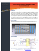
Sensor Output
The following graph represents the typical 0-5V module output per the calibration sequence
above and an idealized 12” eTape sensor input resistance range of 300 to 2000 ohms.
.
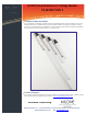
Circuit Diagram
Milone Technologies, Inc - 17 Ravenswood Way - Sewell, New Jersey 08080 - Phone: (856) 270-2688
Email: info@milonetech.com Web: www.milonetech.com
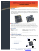
0-5VDC Linear Resistance to Voltage Module
PN-05V00199 REV 2
0
1
2
3
4
5
0 200 400 600 800 1000 1200 1400 1600 1800 2000
Module Output (volts)
12-inch eTape Sensor Output (ohms)
Typical 0-5V Module Output