
Owner`s manual


OM-172 324 Page 10
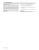
2-3. Rear Panel Connections
1 Receptacle
2 Keyway
3 14-Pin Receptacle (Connec-
tion To Welding Power
Source)
4 17-Pin Receptacle (Connec-
tion To Welding Power Source
With 17-Pin Receptacle)
5 19-Socket Receptacle (Motor/
Shielding Gas Control
Connection To Motor Drive
Assembly)
6 10-Socket Receptacle (Op-
tional Remote Program Select
Connection To Robot Control)
To connect matching interconnect-
ing cord to one of the above recep-
tacles, align keyway, insert plug,
and tighten threaded collar. Con-
nect remaining end of cord to
matching receptacle on applicable
equipment (see Section 2-2).
7 4-Pin Receptacle (Optional
External Voltage Sensing
Connection)
To connect interconnecting cord to
receptacle, align keyway, insert
plug, and tighten threaded collar.
Cord for voltage sensing connec-
tion divides in two. Secure ring ter-
minal on one cord to clamp and at-
tach clamp to work. Secure ring ter-
minal on remaining cord to motor/
drive assembly where weld cable is
connected.
8 Interface Panel (Robot Con-
trol Connection)
Receptacle will vary according to
the robot control being used with
the system. Follow connection
directions included with interface
panel kit.
Ref. S-0003-A / ST-800 962-A
8
3
45
6
7
1
B
M
C
N
L
D
RS
K
E
G
J
F
H
P
T
A
2
Example Receptacle
If optional external voltage sensing connections are used, remove
jumper link from across terminals D and E on internal terminal strip
2T and install jumper link across terminals C and D. See Section 2-4
for the location of 2T.