
Owner`s manual


OM-220 979 Page 12
803 698-E
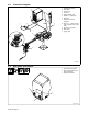
5-3. Connection Diagram
1 Welding Power Source
2 Wire Feeder
3 Gas Cylinder
4 Gas Hose
5 Network Feeder Cable
6 Negative (−) Weld Cable
7 Workpiece
8 Voltage Sensing Lead
(Optional)
. Positive (+) voltage sensing
lead is contained in the motor
cable.
9 Positive (+) Weld Cable
10 Motor Cable
11 Trigger Cable
1
2
3
4
5
7
8
9
6
10
11
11
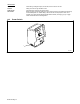
5-4. Rear Panel Connections
Ref. 803 503-A
1 9-Pin Network Receptacle
2 Motor Control/Shielding Gas
Valve Receptacle
3 Rating Label Location
1
2
3