OM-217 834G 2006−06 Processes MIG (GMAW) Welding Description Wire Feeder ROI (Remote Operator Interface) Visit our website at www.MillerWelds.
From Miller to You Thank you and congratulations on choosing Miller. Now you can get the job done and get it done right. We know you don’t have time to do it any other way. That’s why when Niels Miller first started building arc welders in 1929, he made sure his products offered long-lasting value and superior quality. Like you, his customers couldn’t afford anything less. Miller products had to be more than the best they could be. They had to be the best you could buy.
TABLE OF CONTENTS SECTION 1 − SAFETY PRECAUTIONS - READ BEFORE USING . . . . . . . . . . . . . . . . . . . . . . . . . . . . . . . . . . . 1-1. Symbol Usage . . . . . . . . . . . . . . . . . . . . . . . . . . . . . . . . . . . . . . . . . . . . . . . . . . . . . . . . . . . . . . . . . . . . . . . . 1-2. Arc Welding Hazards . . . . . . . . . . . . . . . . . . . . . . . . . . . . . . . . . . . . . . . . . . . . . . . . . . . . . . . . . . . . . . . . . . 1-3.
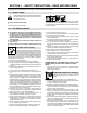
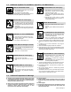
SECTION 1 − SAFETY PRECAUTIONS - READ BEFORE USING som _3/05 Y Warning: Protect yourself and others from injury — read and follow these precautions. 1-1. Symbol Usage Means Warning! Watch Out! There are possible hazards with this procedure! The possible hazards are shown in the adjoining symbols. Y Marks a special safety message. . Means “Note”; not safety related. This group of symbols means Warning! Watch Out! possible ELECTRIC SHOCK, MOVING PARTS, and HOT PARTS hazards.
ARC RAYS can burn eyes and skin. Arc rays from the welding process produce intense visible and invisible (ultraviolet and infrared) rays that can burn eyes and skin. Sparks fly off from the weld. D Wear an approved welding helmet fitted with a proper shade of filter lenses to protect your face and eyes when welding or watching (see ANSI Z49.1 and Z87.1 listed in Safety Standards). D Wear approved safety glasses with side shields under your helmet.
1-3. Additional Symbols For Installation, Operation, And Maintenance FIRE OR EXPLOSION hazard. MOVING PARTS can cause injury. D Do not install or place unit on, over, or near combustible surfaces. D Do not install unit near flammables. D Do not overload building wiring − be sure power supply system is properly sized, rated, and protected to handle this unit. D Keep away from moving parts such as fans. D Keep all doors, panels, covers, and guards closed and securely in place.
1-5. Principal Safety Standards Safety in Welding, Cutting, and Allied Processes, ANSI Standard Z49.1, from Global Engineering Documents (phone: 1-877-413-5184, website: www.global.ihs.com). Boulevard, Rexdale, Ontario, Canada M9W 1R3 (phone: 800−463−6727 or in Toronto 416−747−4044, website: www.csa−international.org). Recommended Safe Practices for the Preparation for Welding and Cutting of Containers and Piping, American Welding Society Standard AWS F4.
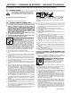
SECTION 2 − CONSIGNES DE SÉCURITÉ − LIRE AVANT UTILISATION fre_som _3/05 Y Avertissement : se protéger et protéger les autres contre le risque de blessure — lire et respecter ces consignes. 2-1. Symboles utilisés Symbole graphique d’avertissement ! Attention ! Cette procédure comporte des risques possibles ! Les dangers éventuels sont représentés par les symboles graphiques joints. Y Indique un message de sécurité particulier . Signifie NOTE ; n’est pas relatif à la sécurité. 2-2.
LES RAYONS D’ARC peuvent entraîner des brûlures aux yeux et à la peau. Le rayonnement de l’arc du procédé de soudage génère des rayons visibles et invisibles intenses (ultraviolets et infrarouges) susceptibles de provoquer des brûlures dans les yeux et sur la peau. Des étincelles sont projetées pendant le soudage. D Porter un casque de soudage approuvé muni de verres filtrants approprié pour protéger visage et yeux pendant le soudage (voir ANSI Z49.1 et Z87.1 énuméré dans les normes de sécurité).
2-3. Dangers supplémentaires en relation avec l’installation, le fonctionnement et la maintenance Risque D’INCENDIE OU D’EXPLOSION. DES ORGANES MOBILES peuvent provoquer des blessures. D Ne pas placer l’appareil sur, au-dessus ou à proximité de surfaces inflammables. D Ne pas installer l’appareil à proximité de produits inflammables. D Ne pas surcharger l’installation électrique − s’assurer que l’alimentation est correctement dimensionnée et protégée avant de mettre l’appareil en service.
2-5. Principales normes de sécurité Safety in Welding, Cutting, and Allied Processes, ANSI Standard Z49.1, de Global Engineering Documents (téléphone : 1-877-413-5184, site Internet : www.global.ihs.com). Boulevard, Rexdale, Ontario, Canada M9W 1R3 (téléphone : 800-463-6727 ou à Toronto 416-747-4044, site Internet : www.csa-international.org). Recommended Safe Practices for the Preparation for Welding and Cutting of Containers and Piping, American Welding Society Standard AWS F4.
SECTION 3 − INTRODUCTION 3-1. Specifications Type of Input Power Welding Power Source Type 40 Volts DC 10 Amperes Axcess Series Wire Feed Speed Range Wire Diameter Range Welding Circuit Rating Overall Dimensions Weight Standard: 40 To 1400 ipm (1.0 To 35.6 mpm) .035 To 1/16 in (0.8 To 1.6 mm) 100 Volts, 750 Amperes, 100% Duty Cycle Length: 7 in (178 mm) 11 lb (5 kg) Max Spool Weight: 60 lb (27 kg) Width: 7 in (178 mm) Height: 12 in (305 mm) SECTION 4 − INSTALLATION 4-1.
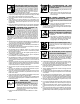
4-2. Installing Insulator Kit Y Turn Off and disconnect input power. 1 2 3 4 5 6 1 ROI Control Insulator Plate Mounting Plate 1/4-20x3/4 in Screw (4) Nylon Shoulder Washer (4) 3/8 in Flat Washer (4) Place insulator plate between ROI base and metal mounting surface. Place nylon shoulder washer over screw. Place flat washer over shoulder washer. 2 Insert hardware assembly through hole in metal mounting base, insulator, and into ROI base (4 locations). Tighten hardware to secure control.
4-3. Remote Operator Interface And Wire Drive Installation Typical Swingarc installation shown; however, various installations are possible depending on the application. 1 1 2 3 4 5 2 5 3 Remote Operator Interface Swingarc Swivel Assembly Boom AA40G Wire Drive Assembly Trigger Cable 5 4 Ref. 803 697-E 4-4.
4-5. Rear Panel Connections 1 2 3 9-Pin Network Receptacle Motor Control/Shielding Gas Valve Receptacle Rating Label Location 2 3 1 Ref. 803 503-A 4-6. 9-Pin Network Receptacle Information 9 F E H I D C 4-7.
4-8. Power Source Display At Power Up 1 Program Time WFS Amps Arc Ctl Sequence Wire Type Gas Type Trigger Hold Power Source Upper Display Lower Display Arc Adjust Process Process Set Up Axcess Volts 1 2 2 Trigger Control Adjust Feeder Set Up Upper Display Lower Display Net Wait DTEC OFF Axcs 300/450/675 Voltage Range 10 44 4-9.
SECTION 5 − OPERATION 5-1. Operational Terms The following is a list of terms and their definitions as they apply to the interface unit in the wire feeder: General Terms: Arc Adjust Term used to represent arc length adjustments in pulse programs. Increasing Arc Adjust increases the actual arc length. Likewise, decreasing arc adjust shortens arc length. Arc Adjust is replaced by volts in MIG programs.
General Terms: Sequence Selecting Sequence will allow setting of preflow, start, crater, and postflow times and parameters. Preflow Setting a time value for gas flow prior to arc start. Start Provides voltage/arc adjust, wire feed rate, and time value for modified arc starts (which is only adjustable with the optional PDA with File Management/WaveWriter software). Crater Allows setting of voltage/arc adjust, wire feed rate, and time value for arc ends.
5-3.
5-4. Program Push Button 1 Program Display The number of the active program is displayed. 2 3 Program Push Button Program Push Button LED The LED lights to indicate that programs can be changed using the Adjust knob. 1 Program Momentarily press button to illuminate LED. To change the program number, rotate Adjust knob to select one of eight programs. 3 Pressing and holding the push button will display the program name, current wire size, wire type, and process.
5-6. Lower Display 5 7 Time 1 6 2 WFS Amps Arc Ctl 3 1 Lower Display The lower display shows WFS (wire feed speed), AMPS (amperage), ARC CTL (arc control), or Time. The feeder displays only preset wire speed at idle (not welding). While welding, the average amperage is displayed. The lower display shows welding sequence time when the Time LED is illuminated.
5-7. Feeder Set Up Push Button 3 4 Sequence Start Time Trigger Control Trigger Hold 1 Crater Time Preflow Time Postflow Time 2 Sequence Diagram Feeder Set Up 1 2 Feeder Set Up Push Button LED Feeder Set Up Push Button • Press button to choose Sequence. Feeder Set Up push-button LED will illuminate. 3 Sequence LED • When the Feeder Set Up button is pressed once, the Sequence LED will illuminate and the upper display will show sequence options.
5-9. Process Set Up Push Button 1 2 3 Process Wire Type Gas Type 3 Process Set Up Push Button Process Set Up LED Program Selection LEDs 2 1 Process Set Up • Press the Process Set Up push button the first time will illuminate the button LED and the Process LED. The upper and lower displays will be used for Accu-pulse and only the lower display for MIG, Pulse and RMD (optional) to show the current process installed in this program. To change process, turn the adjust knob.
5-10. Jog/Purge 1 2 3 Jog/Purge Push Button Adjust Control Gun Trigger Receptacle 2 3 1 803 693-A The Jog/Purge switch provides the following functions: • Pressing left side of the Jog/Purge switch allows the operator to feed wire without energizing the weld power or gas valve circuit. The wire will feed at a 60 ipm rate for 3 seconds, then the rate ramps up to 700 ipm until the Jog switch is released. • The unit also provides the ability to jog the wire feeder by means of the gun trigger.
5-11. Reset Mode Program . Reset mode is not active when Program Lock is enabled. RST Volts Time NO WFS Amps The reset mode allows the operator to reload factory program settings for all eight active programs in the unit. Arc Adjust Arc Ctl . System configuration data will be Sequence Trigger Control Process Wire Type Gas Type Trigger Hold Process Set up Adjust lost during the Reset operation.
SECTION 6 − SETTING SEQUENCE PARAMETERS 6-1. Sequence Parameters In A Program . For more information on Sequence mode, see Feeder Set Up Push Button in Section 5-7. Sequence Weld Time can only be set by using an optional PDA with File Management/WaveWriter software. Parameters Volts/Arc Adjust Seconds If time is set to zero in any timed sequence, the sequence is skipped. 1. Preflow Off-5.0 . Maximum IPM may actually be 2. Postflow Off-5.0 IPM 3. Start 10.0-44.0/ 0-99 40-1400 Off-5.0 4.
SECTION 7 − MAINTENANCE 7-1. Routine Maintenance Y Disconnect power before maintaining. n = Check Z = Change ~ = Clean * To be done by Factory Authorized Service Agent Every 3 Months Every 6 Months l Unreadable Labels OR ~ Inside Unit OM-217 834 Page 24 nl Cracked Parts l = Replace nl Cords . Maintain more often during severe conditions.
7-2. Diagnostics The following error messages are shown on the upper and lower displays to indicate specific errors. Explanations are in the text below: ERR ERR ERR ERR ERR ERR TACH MOTR WFS STRT STOP FLOW Indicates a tachometer error. Indicates a motor error. Indicates a wire feed speed error. Indicates an arc start error. Indicates an arc stop error. Indicates a gas flow error. ERR ERR ERR ERR ERR ERR COOL GND STUK TEMP LINE ARC Indicates a coolant flow error.
7-2. Diagnostics (Continued) WELD MOTR PLS OVER LOW E WAIT COM WAIT CRNT WFS STOP Indicates a weld cycle wait error. Indicates a motor communication error. Indicates a UIM communication error. Indicates an overcurrent error. RMD OVER REL ERR DONE AVER TRIG UNKN Indicates an arc error. Indicates an over Indicates a trigger average current error. closed error. WELD WAIT • The weld wait error indicates unit was not ready for a weld sequence. Press Jog/ Purge button to clear error.
Notes OM-217 834 Page 27
SECTION 8 − ELECTRICAL DIAGRAM Figure 8-1.
214 842-E OM-217 834 Page 29
SECTION 9 − PARTS LIST . Hardware is common and not available unless listed. 20 7 6 5 4 1 3 2 8 10 9 13 19 11 14 15 12 16 18 17 803 696-B Figure 9-1. Remote Operator Interface Item No. Dia. Mkgs. Part No. Description Quantity Figure 9-1. Remote Operator Interface ... 1 ............... ..................... ... 2 ............... . . . 3 . . . . PC5 . . . . . . . . 4 . . . . PC7 . . . . . ... 5 ............... ... 6 ............... . . . 7 . . . . PC6 . . . . . ... 8 ............... . . .
Item No. Dia. Mkgs. Part No. Description Quantity Figure 9-1. Remote Operator Interface (Continued) . . . 14 . . . . PC1 . . . . . . . . 15 . . . . RC4 . . . . . . . . 16 . . . . . . . . . . . . . . . . . . 17 . . . . . . . . . . . . . . . . . . 18 . . . . . S2 . . . . . . ..................... ..................... ..................... . . . 19 . . . . . . . . . . . . . . . . . . 20 . . . . . . . . . . . . . . . . . . . . . . . . PLG47 . . . . . . . . . . . . . PLG48 . . . . . . . . . . . . . .
Notes
Notes
Notes
Effective January 1, 2006 (Equipment with a serial number preface of “LG” or newer) Warranty Questions? Call 1-800-4-A-MILLER for your local Miller distributor. Your distributor also gives you ... Service You always get the fast, reliable response you need. Most replacement parts can be in your hands in 24 hours. Support Need fast answers to the tough welding questions? Contact your distributor. The expertise of the distributor and Miller is there to help you, every step of the way.
Owner’s Record Please complete and retain with your personal records. Model Name Serial/Style Number Purchase Date (Date which equipment was delivered to original customer.) Distributor Address City State Zip For Service Contact a DISTRIBUTOR or SERVICE AGENCY near you. Always provide Model Name and Serial/Style Number. Contact your Distributor for: Welding Supplies and Consumables Options and Accessories Personal Safety Equipment Service and Repair Miller Electric Mfg. Co.