
Owner`s manual


OM-223 528 Page 25
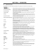
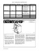
5-9. Adjust Knob
Adjust
1
1 Adjust Knob
The Adjust knob is used to change
functions and parameters. Refer to
the front panel sections for
information regarding use of this
control.
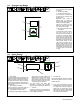
5-10. Process Set Up Push Button
. Holding the Process Set Up push button
in during power up will display the soft-
ware versions of each circuit board. Turn
the Adjust knob to cycle through all three
circuit boards to view each software revi-
sion. Press the Feeder Set Up push bu-
toon to allow the unit to continue its power
up procedure.
• Press the Process Set Up push button the
first time will illuminate the button LED and
the Process LED. The upper and lower
displays will be used for Accu-pulse and
only the lower display for MIG, Pulse and
RMD (optional) to show the current process
intalled in this program. To change process,
turn the adjust knob.
• Pressing the Process Set Up push button a
second time will illuminate the Wire Type
LED and the lower display will show wire
types available for selected processes (see
Table 5-1 for wire abbreviation). To make a
selection, turn the Adjust knob.
• Pressing the Process Set Up push button a
third time will keep Wire Type LED lit and the
upper display will show wire alloy type (see
Table 5-1 for alloy types). The upper display
push-button LED will be flashing indicating
that turning the Adjust knob will change the
alloy type for the selected process and wire
type.
• Pressing the Process Set Up push button a
fourth time will keep Wire Type LED lit and
the upper display will show wire size. The
upper display push button will be flashing
indicating that turning the Adjust knob will
select wire sizes available for that particular
process and wire type.
• Pressing the Process Set Up push button a
fifth time will illuminate the Gas Type LED
and the lower display will show GAS and the
upper display will show gas selection (see
Table 5-1 for gas abbreviations). To make a
gas type selection, turn the Adjust knob.
• If any of the Process, wire type, alloy type,
wire size, or gas type was changed, then
pressing the Process Set Up push button a
sixth time will show PROG in the upper
display and LOAD in the lower display. The
new program would be loaded for that
particular program in slot 1 thru 8. If no
changes were made to any setup items, no
program will be loaded, and unit will return
to standby mode.
• If a custom program is loaded using an
optional PDA with File Management
software, the Program Display will have a
“C” in front of the program number. This
indicates that the program is not a factory
default program and has been modified. By
selecting or changing any process variable
and performing a program load will restore
the program back to the factory default
program.
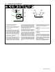
1
3
2
1 Process Set Up Push Button
2 Process Set Up LED
3 Program Selection LEDs
Process
Wire Type
Gas Type
Process Set Up