
Owner`s manual


OM-223 528 Page 13
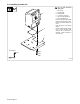
4-3. Rear Panel Connections
804 091-A
1 Input/Output Receptacle
RC100
2 Motor Control/Shielding Gas
Valve Receptacle RC8
3 9-Pin Network Receptacle
RC1
4 Rating Label Location
3
2
4
1
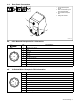
4-4. 9-Pin Network Receptacle RC1 Information
9
Pin Pin Information
A
B
I
C
H
D
G
E
F
A Capacitor C1 to ground
B Shield
C Volt sense
D Can low
E Can high
F +24 volts DC common
G + 24 volts DC
H Motor voltage −40 volts
I Motor voltage +40 volts
4-5. 10-Socket Motor Receptacle RC8 Information
B
D
F
K
E
J
A
G
C
H
Socket Socket Information
A Not used
B Motor common
C +1.75 volts DC ±0.2 volts when tach A encoder is rotating
D +1 volt DC per 35 IPM with respect to pin B
E Tach common
F Gas valve common
G Electrode sense
H +5 volts DC tach
J +40 volts DC gas valve