OM-884 February 2000 Processes Automatic Welding Description Automatic Welding Interface A.B.B. Robot Interface Gas Control Hub And Spindle Visit our website at www.MillerWelds.
From Miller to You Thank you and congratulations on choosing Miller. Now you can get the job done and get it done right. We know you don’t have time to do it any other way. That’s why when Niels Miller first started building arc welders in 1929, he made sure his products offered long-lasting value and superior quality. Like you, his customers couldn’t afford anything less. Miller products had to be more than the best they could be. They had to be the best you could buy.
TABLE OF CONTENTS SECTION 1 – SAFETY PRECAUTIONS - READ BEFORE USING . . . . . . . . . . . . . . . . . . . . . . . . . . . . 1-1. Symbol Usage . . . . . . . . . . . . . . . . . . . . . . . . . . . . . . . . . . . . . . . . . . . . . . . . . . . . . . . . . . . . . . . . 1-2. Arc Welding Hazards . . . . . . . . . . . . . . . . . . . . . . . . . . . . . . . . . . . . . . . . . . . . . . . . . . . . . . . . . . 1-3. Additional Symbols For Installation, Operation, And Maintenance . . . . . . . . . . . . . . . .
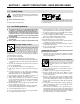
SECTION 1 – SAFETY PRECAUTIONS - READ BEFORE USING som _nd_5/97 1-1. Symbol Usage Means Warning! Watch Out! There are possible hazards with this procedure! The possible hazards are shown in the adjoining symbols. Y Marks a special safety message. . Means “Note”; not safety related. This group of symbols means Warning! Watch Out! possible ELECTRIC SHOCK, MOVING PARTS, and HOT PARTS hazards. Consult symbols and related instructions below for necessary actions to avoid the hazards. 1-2.
ARC RAYS can burn eyes and skin. Arc rays from the welding process produce intense visible and invisible (ultraviolet and infrared) rays that can burn eyes and skin. Sparks fly off from the weld. D Wear a welding helmet fitted with a proper shade of filter to protect your face and eyes when welding or watching (see ANSI Z49.1 and Z87.1 listed in Safety Standards). D Wear approved safety glasses with side shields under your helmet.
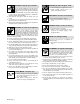
1-3. Additional Symbols For Installation, Operation, And Maintenance FIRE OR EXPLOSION hazard. MOVING PARTS can cause injury. D Do not install or place unit on, over, or near combustible surfaces. D Do not install unit near flammables. D Do not overload building wiring – be sure power supply system is properly sized, rated, and protected to handle this unit. D Keep away from moving parts such as fans. D Keep all doors, panels, covers, and guards closed and securely in place.
1-5. EMF Information Considerations About Welding And The Effects Of Low Frequency Electric And Magnetic Fields Welding current, as it flows through welding cables, will cause electromagnetic fields. There has been and still is some concern about such fields.
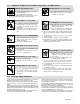
SECTION 1 – CONSIGNES DE SECURITE – LIRE AVANT UTILISATION som _nd_fre 5/97 1-1. Signification des symboles Signifie Mise en garde ! Soyez vigilant ! Cette procédure présente des risques de danger ! Ceux-ci sont identifiés par des symboles adjacents aux directives. Y Identifie un message de sécurité particulier. . Signifie NOTA ; n’est pas relatif à la sécurité.
LES RAYONS DE L’ARC peuvent provoquer des brûlures dans les yeux et sur la peau. Le rayonnement de l’arc du procédé de soudage génère des rayons visibles et invisibles intenses (ultraviolets et infrarouges) susceptibles de provoquer des brûlures dans les yeux et sur la peau. Des étincelles sont projetées pendant le soudage. D Porter un casque de soudage muni d’un écran de filtre approprié pour protéger votre visage et vos yeux pendant le soudage ou pour regarder (voir ANSI Z49.1 et Z87.
1-3. Dangers supplémentaires en relation avec l’installation, le fonctionnement et la maintenance Risque D’INCENDIE OU D’EXPLOSION. DES ORGANES MOBILES peuvent provoquer des blessures. D Ne pas placer l’appareil sur, au-dessus ou à proximité de surfaces infllammables. D Rester à l’écart des organes mobiles comme le ventilateur. D Maintenir fermés et fixement en place les portes, panneaux, recouvrements et dispositifs de protection.
1-4. Principales normes de sécurité Safety in Welding and Cutting, norme ANSI Z49.1, de l’American Welding Society, 550 N.W. Lejeune Rd, Miami FL 33126 Safety and Health Sandards, OSHA 29 CFR 1910, du Superintendent of Documents, U.S. Government Printing Office, Washington, D.C. 20402. Recommended Safe Practice for the Preparation for Welding and Cutting of Containers That Have Held Hazardous Substances, norme AWS F4.1, de l’American Welding Society, 550 N.W.
SECTION 2 – INSTALLATION 2-1. Specifications Dimensions Weight Component Height Width Depth Net Robot Interface 22-1/2 in. (572 mm) 16-1/2 in.♦ (419 mm) 6-1/4 in.* (159 mm) 38 lbs. (17 kg) Gas/Current Sensing Control 4-1/2 in. (108 mm) 5-1/2 in. (140 mm) 10-1/2 in. (267 mm) 5 lbs. (2.3 kg) Spool Support Assembly+ 13-3/4 in. (349 mm) 8-3/4 in. (222 mm) 8-1/2 in. (216 mm) 6 lbs. (2.7 kg) ♦Add 2-1/4 in. (57 mm) for brake resistor. Ship Total 61 lbs. (27.
2-3. Connection Diagram 2 1 14 1 2 3 RC17 RC13 4 RC12 RC9 12 5 11 3 4 5 6 7 8 9 10 11 12 13 14 10 13 Robot Interface 115 Volts AC/Contactor And Output Control Cord Welding Power Source Weld Cables Shielding Gas Supply Electrode (Welding Wire) Work Wire Drive Assembly Motor Control Cord Gas Control Gas Control Cord Arc Sensing Cord Arc Failure Connection Inside Robot Control Unit Robot Interface Connections To Robot Control Unit 6 9 8 7 Ref. S-0290 2-4.
2-5. Shielding Gas Connection To Regulator/Flowmeter 1 2 3 1 6 OR Argon Gas 5 2 4 3 Tools Needed: 7 1-1/8, 5/8 in 8 CO2 Gas Obtain gas cylinder and chain to running gear, wall, or other stationary support so cylinder cannot fall and break off valve. 1 Cap 2 Cylinder Valve Cylinder 4 Regulator/Flowmeter 5 Make sure flow adjust is closed when opening cylinder to avoid damage to the flowmeter. Gas Hose Connection Fitting has 5/8-18 right-hand threads. Obtain and install gas hose.
2-7. Arc Sensing Connections Locate arc sensing cord, and connect 4-socket plug to receptacle RC12 on robot interface. To make connection, align keyway, insert plug, and tighten threaded collar. 1 1 2 3 4 5 6 Positive Weld Output Terminal On Welding Power Source Weld Cable Lug Location Arc Sensing Lead Ring Terminal Location Connect lead with ring terminal to welding power source Positive (+) weld output terminal as shown.
2-9. 24-Socket Receptacle RC17 Information Socket* D J Q C H P V N U Z Y A Provides connection to 2TA; for customer use. B Current Detect output to robot control unit with respect to Socket D; isolated CR1 contacts rated 1A at 120 VAC. D Current Detect output to robot control unit with respect to Socket B; isolated CR1 contacts rated 1A at 120 VAC. E Contactor Control; +24 volts dc input from robot control unit with respect to Socket J (Circuit Common).
2-10. Arc Failure Light Connections . Arc Failure light on robot inter- face front panel turns on and off by a signal from robot control unit. Obtain proper length of 18 gauge/2-conductor cord for this connection.
2-11. Matching Digital Voltage Control (DVC) Board To Welding Power Source 1 2 DVC Board PC1 DIP Switch 1 2 DVC SWITCH SETTINGS S2 1 2 1 DELTAWELD 300 S1 2 3 ON ON 4 DELTAWELD 451, 450 O ON DELTAWELD 651, 650 O ON ON MAXTRON 300, 400 ON ON ON MAXTRON 450 ON XMT 200/300 ON ON ON ARC PAK 350 ON ON ON ON SHOPMASTER 300 DIMENSION 400 ON ON ON ON PULSTAR 450 ∆ 5 ON ∆ ON Tools Needed: ON Non-Conductive ON O – On For Optional Soft Start. Turn Off S1 -3.
2-12. Hub Assembly Installation 1 2 3 4 5 6 7 2 3 4 Spool Support Hub Support Shaft Retaining Ring Hub Assembly Brake Washer Fiber Washer Hex Nut Install hub assembly as shown. Tighten hex nut until a slight drag is felt while turning hub. 5 6 7 1 Tools Needed: 9/16 in ST-126 870-A 2-13. Installing Spool-Type Wire And Adjusting Hub Tension 1 2 3 4 1 Retaining Ring Wire Spool Hole In Spool Hub Remove retaining ring and slide spool onto hub. Turn spool until hub pin fits hole in spool.
2-14. Installing Optional Reel-Type Wire 1 2 3 1 2 3 4 5 6 7 4 5 Retaining Ring Lock Spanner Nut Wire Retainer Welding Wire Wire Reel Hub Remove retaining ring. Pull lock and turn. Remove spanner nut, wire retainer, and wire reel from hub. 6 To install wire lay wire reel on flat surface and install wire as shown. Tighten spanner nut until lock is in position over hole in wire retainer. Pull lock and turn to insert locking pin into wire retainer. Unlocked 7 Slide wire reel assembly onto hub.
3-2. Work Clamp 1 1 Tools Needed: Work Clamp Connect work clamp to a clean, paint-free location on workpiece, as close to weld area as possible. Use wire brush or sandpaper to clean metal at weld joint area. Use chipping hammer to remove slag after welding. sb4.1 2/93 3-3. Front Panel Controls 1 Power Switch Use this switch to turn unit On and Off. 5 6 2 Purge Push Button Momentarily energizes gas solenoid to purge air from gun shielding gas line, or to adjust shielding gas regulator.
3-4. Indicator Lights 1 Gas Indicator Light Gas sight turns on when the gas valve is energized to indicate shielding gas flow. 2 Contactor Indicator Light Contactor light turns on when the welding power source contactor is energized to indicate that weld output is available. 3 Wire Feed Indicator Light WIRE FEED light turns on when the wire drive motor is energized to indicate that wire is feeding.
3-5. Burnback Control 2 1 Burnback circuitry keeps welding wire from sticking to workpiece after arc is extinguished. This circuitry keeps weld output on welding wire from 0 to 0.25 seconds after wire has stopped feeding. This delay action permits welding wire to burn back to a point where it neither sticks to workpiece or contact tip. To adjust burnback time, open front access door. 1 2 Interface Board PC3 Potentiometer R37 Rotate R37 clockwise to increase burnback time.
SECTION 4 – SEQUENCE OF OPERATION 4-1. Input/Output Signals Robot interface receives input signals for contactor control, gas control, jog, welding volts, and wire speed. It also receives a signal to initiate a check to see if wire is stuck to workpiece at end of a weld. Robot interface sends output signals to robot control unit for current sense, wire stuck, and weld standby.
SECTION 5 – MAINTENANCE & TROUBLESHOOTING 5-1. Routine Maintenance Y Disconnect power before maintaining. 3 Months Repair or replace cracked weld cable. Clean and tighten weld terminals. Replace unreadable labels. Replace cracked parts. Check 14-pin cord. Check gas hose and fittings. Check gun cable. 6 Months Blow out or vacuum inside. During heavy service, clean monthly. Clean drive rolls. OR 5-2. Replacing The Hub Assembly Turn Off weld control and welding power source.
5-3. Overload Protection 3 If fuse F1 opens, the robot interface shuts down. To check or change F1, proceed as follows: 1 2 3 Fuse Holder Cover Fuse F1 (See Parts List For Rating) Circuit Breaker CB1 CB1 protects the wire feed motor from overload. If CB1 opens, the wire feed motor stops. Check for jammed wire, binding drive gear, or misaligned drive rolls. Correct problem. Allow cooling period and manually reset breaker. 1 Push And Turn 2 Pull Out And Replace F1 Push And Turn Ref.
5-4. Display Board PC4 Meter Check Check points are provided on display board PC4 for checking power supply and input command to meters. 1 Display Board PC4 2 Meter To make checks at display board, open front access door. CB1 protects the wire feed motor from overload. If CB1 opens, the wire feed mo- tor stops. Check for jammed wire, binding drive gear, or misaligned drive rolls. Correct problem. Allow cooling period and manually reset breaker.
5-5. Troubleshooting Y Disconnect power before troubleshooting Trouble No arc voltage control. Remedy Check and secure output control connections (see Section 2-4). Check and secure arc sensing connections (see Section 2-7). Check robot command voltage at Isolation Board PC5. Command voltage should be 0-10 vdc between sockets Y (common) and Z at RC17. Check robot peak command current at Isolation Board PC5. Peak command current should be 0-10 vdc between sockets R and S (common) at RC17.
5-6. Use Of Indicator Lights For Troubleshooting On Gas flows: System normal (on.) On Contactor closed: System normal (on). On Wire feeds: System normal (on). On Arc started: System normal (on). On No arc: Check weld parameters. OM-884 Page 26 Gas Indicator Light Gas does not flow: Check gas valve operation. Gas flows: Check gas valve operation and gas line for leaks. Check interface board PC3. Contactor Indicator Light Contactor open: Check interconnecting cords. Check interface board PC3.
SECTION 6 – ELECTRICAL DIAGRAMS 151 242-E Figure 6-1.
SECTION 7 – PARTS LIST . Hardware is common and 3 not available unless listed. 4 10 11 12 13 14 15 2 6 1 7 5 8 9 16 17 18 5 36 35 29 28 19 27 34 21 26 33 23 32 24 31 Fig 7-2 22 20 25 30 SC-119 647-A Figure 7-1. Control Box Item No. Dia. Mkgs. Part No. Description Quantity Figure 7-1. Control Box . . . 1 . . . . PLG24 . . . . . . 2 . . . . PLG20 . . . . . . 3 . . . . . PC4 . . . . ... 4 ............... . . . 5 . . . . PB1,2 . . . . . . . 6 . . . . . CB1 . . . . . . . 7 .
Item No. Dia. Mkgs. Part No. Description Quantity Figure 7-1. Control Box (Continued) . . . 19 . . . . . . . . . . . . . . . 175 115 . . CABLE, interconnecting (consisting of) . . . . . . . . . . . . . . . . . . . . . . . . . . . . 1 . . . . . . . . . . . . . . . . . . . . . 152 370 . . . . HOUSING PLUG & SOCKETS, (consisting of) . . . . . . . . . . . . . . . . . . . 1 . . . . . . . . . . . . . . . . . . . . . 079 739 . . . . . CONNECTOR, circ clamp str rlf . . . . . . . . . . . . . . . . . . . . . . .
. Hardware is common and not available unless listed. 3 2 4 1 5 6 26 7 25 8 24 21 22 23 9 10 12 16 15 17 18 11 19 12 20 14 13 Figure 7-2.
Item No. Dia. Mkgs. Part No. Description Quantity Figure 7-2. Control Panel, w/Components (Fig 7-1 Item 23) . . . 1 . . . . . PC2 . . . . 071 642 . . . 2 . . . . . RC5 . . . . 117 374 . . . 3 . . . . . . . . . . . . . . . 009 335 . . . 4 . . . . . . . . . . . . . . . 112 473 . . . 5 . . . . . . . . . . . . . . . 605 741 . . . 6 . . . . . . R3 . . . . . 079 497 . . . 7 . . . . . . R1 . . . . . 030 651 . . . 8 . . . . . . T2 . . . . . 116 847 . . . 9 . . . . . CR1 . . . . 109 006 . . . 10 . . . . . .
Item No. Dia. Mkgs. Part No. Description Quantity Figure 7-3. Hub & Spindle Assembly . . . 1 . . . 072 094 . . . 2 . . . 058 427 . . . 3 . . . 185 072 . . . 4 . . . 010 233 . . . 5 . . . 057 971 . . . 6 . . . 010 191 . . . 7 . . . 058 628 . . . 8 . . . 058 428 . . . 9 . . . 135 205 . . . 10 . . +092 989 . . . . . . . . . 134 464 . . . 11 . . ♦108 008 . . . 12 . . . 124 900 . . . 13 . . . 168 104 . . . . . . . . . 166 594 . . . 14 . . . 168 103 . . HUB & SPINDLE, (consisting of) . . . . . . . . . . . .
Item No. Dia. Mkgs. Part No. Description Quantity Figure 7-4. Control Box, Gas ... ... ... ... ... ... ... ... ... ... ... ... ... ... ... ... 1 2 3 4 5 6 7 8 9 10 11 12 13 14 15 16 . . . . . . . . . . . . . 134 327 . . . . . . . . . . . . +079 682 . . . REED . . . 140 786 . . . . . . . . . . . . . 109 021 . . . . . . . . . . . . . . 115 104 . . . . . . . . . . . . . 010 494 . . . . . . . . . . . . . 057 358 . . . . . . . . . . . . . 010 604 . . . . . . . . . . . . . 602 934 . . . . . . . . . . . . .
Notes OM-884 Page 34
Effective January 1, 2000 (Equipment with a serial number preface of “LA” or newer) This limited warranty supersedes all previous Miller warranties and is exclusive with no other guarantees or warranties expressed or implied. Warranty Questions? Call 1-800-4-A-MILLER for your local Miller distributor. Your distributor also gives you ... Service You always get the fast, reliable response you need. Most replacement parts can be in your hands in 24 hours.
Owner’s Record Please complete and retain with your personal records. Model Name Serial/Style Number Purchase Date (Date which equipment was delivered to original customer.) Distributor Address City State Zip For Service Call 1-800-4-A-Miller or see our website at www.MillerWelds.com to locate a DISTRIBUTOR or SERVICE AGENCY near you. Always provide Model Name and Serial/Style Number.