
User's Manual
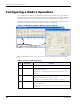
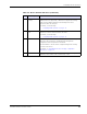
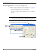
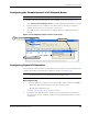
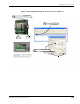
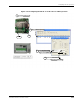
Table Of Contents
- MeshScape™ RK-5424-5 Reference Kit for 2.4 GHz MeshScape Systems User's Guide
- Contents
- About This Guide
- 1: Introduction
- 2: Installing the MeshScape System
- 3: Running MeshScape Network Monitor
- MeshScape Network Monitor Overview
- Configuring a Node’s Operation
- Labeling an End Node or Mesh Node
- Configuring Persistence Attributes
- Selecting a Com Port on the Host PC
- Configuring Serial and ADC Data Formats
- Turning Event Tracking On/Off
- Broadcasting Data to All Nodes.
- Creating an Event Log File
- Viewing the Contents of an Event Log File
- Viewing MeshScape Statistics
- 4: Using the MeshScape API
- A: Running the Demo Application
- B: Using MeshScape Programmer
- Glossary
- Index

3-12 Millennial Net
Running MeshScape Network Monitor
Configuring UART Operation
The following procedures describes how to use the End Node’s digital I/O connections or the
Mesh Node’s UART connector for serial/UART communications (see
Figure 3-15). Refer to the
technical specification sheets for the End Node and Mesh Node for additional information
required when using the device for serial communications.
1. Connect to the following:
– End Node’s P9 terminal block (pins DIO 0–DIO 3, GND).
Pin 1 - Gnd
Pin 2 - DIO 0 RXD (Output)
Pin 3 - DIO 1 TXD (Input)
Pin 4 - DIO 2 RTS (Input)
Pin 5 - DIO 3 CTS (Output)
– Mesh Node’s terminal block connector (pins DIO 0-DIO 3, GND).
2. From MeshScape Network Monitor, double-click on the desired device from the list of
discovered sensor nodes. The Device window is opened, displaying the device’s current
configuration.
3. From the Config panel, select Serial Data: Digital UART, then Update. The UART
terminal block is ready for UART operation (digital I/O function is disabled).
4. (optional) To send serial data (HEX, DEC, or ASCII) to the node, enter the data in the Out
panel, then select Send Data.
Note:
The End Node supports the following serial communication parameters:
9600 bps, 8 data bits, no parity, 1 stop bits
The mesh node supports the following serial communication parameters:
9600 bps, 8 data bits, no parity, 2 stop bits
Serial data and digital I/O are mutually exclusive operations for end nodes.