
User's Manual
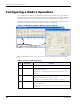
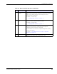
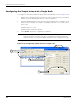
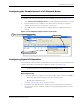
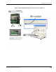
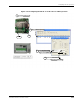
Table Of Contents
- MeshScape™ RK-5424-5 Reference Kit for 2.4 GHz MeshScape Systems User's Guide
- Contents
- About This Guide
- 1: Introduction
- 2: Installing the MeshScape System
- 3: Running MeshScape Network Monitor
- MeshScape Network Monitor Overview
- Configuring a Node’s Operation
- Labeling an End Node or Mesh Node
- Configuring Persistence Attributes
- Selecting a Com Port on the Host PC
- Configuring Serial and ADC Data Formats
- Turning Event Tracking On/Off
- Broadcasting Data to All Nodes.
- Creating an Event Log File
- Viewing the Contents of an Event Log File
- Viewing MeshScape Statistics
- 4: Using the MeshScape API
- A: Running the Demo Application
- B: Using MeshScape Programmer
- Glossary
- Index

3-10 Millennial Net
Running MeshScape Network Monitor
3. From the Digital I/O panel, select Input on each of the desired digital channels to use as
inputs (DIO 0—DIO 3), then select Update.
MeshScape Network Monitor displays the digital information for the node in the Digital
I/O Data column, where On = output channel and In = input channel (n = 1 or 0).
Digital Output Setup
1. Connect the digital signal destination devices to the connectors (DIO 0–DIO 3) and
ground (GND) of the following:
– End Node’s terminal block (P9 located on terminal board).
Pin 1 - Gnd
Pin 2 - DIO 0 RXD (Output)
Pin 3 - DIO 1 TXD (Input)
Pin 4 - DIO 2 RTS (Input)
Pin 5 - DIO 3 CTS (Output)
– Mesh Node’s terminal block connector.
See Figure 3-14 on page 3-11 for connector locations.
2. From MeshScape Network Monitor, double-click on the desired device from the list of
discovered sensor nodes. The Device window is opened, displaying the device’s current
configuration.
3. From the Digital I/O panel, select Output on each of the desired digital channels to use
as outputs (DIO 0—DIO 3).
4. Set the output signal high or low using the 1/0 box located next to the desired Output
button:
– Selected = 1 (output is set high)
– Not selected = 0 (output is set low)
5. Select Update.
MeshScape Network Monitor displays the digital information for the node in the Digital
I/O Data column, where On = output channel and In = input channel (n = 1 or 0).
Note:
Input signals should not be applied when the end node is switched off. Since the
node is an extremely low power device, it’s possible that the input signal voltages
will keep the microcontroller active, preventing it from resetting properly when
switched back on. Also, when switched off, the terminal board will ground certain
pins, which can cause excessive current drain for the external peripheral connected
to it.