
User's Manual


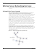
Table Of Contents
- MeshScape™ RK-5424-5 Reference Kit for 2.4 GHz MeshScape Systems User's Guide
- Contents
- About This Guide
- 1: Introduction
- 2: Installing the MeshScape System
- 3: Running MeshScape Network Monitor
- MeshScape Network Monitor Overview
- Configuring a Node’s Operation
- Labeling an End Node or Mesh Node
- Configuring Persistence Attributes
- Selecting a Com Port on the Host PC
- Configuring Serial and ADC Data Formats
- Turning Event Tracking On/Off
- Broadcasting Data to All Nodes.
- Creating an Event Log File
- Viewing the Contents of an Event Log File
- Viewing MeshScape Statistics
- 4: Using the MeshScape API
- A: Running the Demo Application
- B: Using MeshScape Programmer
- Glossary
- Index

RK-5424-5 Reference Kit User’s Guide xi
Figures
Figure 1-1. Untethered, mobile ad hoc network nodes................................................... 1-2
Figure 1-2. Basic wireless sensor network components................................................... 1-4
Figure 1-3. Adding a mesh node module ....................................................................... 1-4
Figure 1-4. MeshScape system core elements................................................................. 1-6
Figure 2-5. MeshGate components ................................................................................ 2-3
Figure 2-6. Mounting the MeshGate to a DIN rail........................................................... 2-6
Figure 2-7. Mesh node components............................................................................... 2-8
Figure 2-8. End node and terminal board (top and bottom views) ................................ 2-12
Figure 2-9. Using Windows Start menu to launch MeshScape Network Monitor .......... 2-16
Figure 3-10. Sample MeshScape Network Monitor window ............................................. 3-2
Figure 3-11. MeshScape Network Monitor’s Device window ............................................ 3-6
Figure 3-12. Configuring sample interval of single node................................................... 3-8
Figure 3-13. Configuring sample interval of all nodes....................................................... 3-9
Figure 3-14. Configuring End Node or mesh node for digital I/O .................................... 3-11
Figure 3-15. Configuring End Node or mesh node for UART operation .......................... 3-13
Figure 3-16. Configuring End Node/Mesh Node for analog I/O....................................... 3-15
Figure 3-17. Displaying I/O information using Watch function........................................ 3-16
Figure 3-18. Labeling an End Node or Mesh Node ......................................................... 3-18
Figure 3-19. Configuring node persistence attributes ..................................................... 3-19
Figure 3-20. Selecting com port on host PC ................................................................... 3-20
Figure 3-21. Configuring serial and ADC data formats ................................................... 3-21
Figure 3-22. Turning device event tracking on/off .......................................................... 3-22
Figure 3-23. Broadcasting data to all nodes ................................................................... 3-24
Figure 3-24. Configure an event log file......................................................................... 3-25
Figure 3-25. View contents of event log file ................................................................... 3-26
Figure 3-26. Viewing MeshScape statistics ..................................................................... 3-29
Figure 4-1. Using the MeshScape API............................................................................. 4-2
Figure 4-2. MeshScape API directories............................................................................ 4-3
Figure A-1. MeshScape Demo main window .................................................................. A-2
Figure A-2. End node terminal board with kele temperature sensor................................ A-3
Figure B-1. Connecting MeshGate programming cable to a mesh node ......................... B-3
Figure B-2. Connecting MeshGate programming cable to an end node.......................... B-3
Figure B-3. Module programming terminal board .......................................................... B-4
Figure B-4. The MeshScape Programmer main window.................................................. B-6