
User Manual
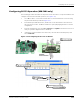
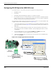
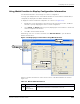
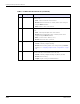
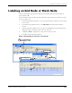
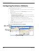
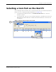
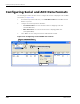
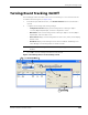
Table Of Contents
- RK-5409-5 Reference Kit for 916 MHz MeshScape™ Systems
- Contents
- About This Guide
- 1: Introduction
- 2: Installing the MeshScape System
- 3: Running MeshScape Network Monitor
- MeshScape Network Monitor Overview
- Configuring a Node’s Operation
- Configuring Sample Interval of Single Node
- Configuring Sample Interval of all Network Nodes
- Configuring Digital I/O Operation
- Configuring UART Operation
- Configuring AD (analog-to-digital) Converter Operation
- Configuring RS-232 Operation (MN-5409 only)
- Configuring RS-485 Operation (MN-5409 only)
- Using Watch Function to Display Configuration Information
- Labeling an End Node or Mesh Node
- Configuring Persistence Attributes
- Selecting a Com Port on the Host PC
- Configuring Serial and ADC Data Formats
- Turning Event Tracking On/Off
- Broadcasting Data to All Nodes.
- Creating an Event Log File
- Viewing the Contents of an Event Log File
- Viewing MeshScape Statistics
- 4: Using the MeshScape API
- A: Sample Application
- B: Performing Firmware Upgrades and Configuring Device IDs
- Glossary
- Index

3-18 Millennial Net
Running MeshScape Network Monitor
B A-D Channels This panel displays the following information for each analog-to-digital
channel (0–3):
• State: Current on/off state of the channel
• Desired: Desired on/off state of channel, which can be changed
using the Device window.
• Value: Numeric values of the channel.
C DIO Channels This panel displays the following information for each digital channel
(0–3):
• State: Current input/output state of the channel
• Desired: Desired input/output state of channel, which can be
changed using the Device window.
• Value: I/O values of the channel (1 or 0).
• Desired: Desired I/O value of channel.
D Sampling Interval This panel displays the following sampling interval information:
• Current: Currently configured setting.
• Desired: Desired setting, which can be changed using the Device
window (see
’Configuring Sample Interval of Single Node’ on page
3-8).
E Serial Data This panel displays the following serial data information of data received
from the node (In) or transmitted to the node (Out):
• Current: Currently configured setting (Off, RS-232, RS-485)
• Desired: Desired setting
• Length: Length of string received/transmitted.
Table 3-7. Watch window functions (continued)
Item Description Function