
User Manual
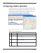
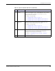
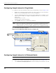
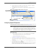
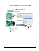
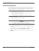
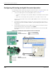
Table Of Contents
- RK-5409-5 Reference Kit for 916 MHz MeshScape™ Systems
- Contents
- About This Guide
- 1: Introduction
- 2: Installing the MeshScape System
- 3: Running MeshScape Network Monitor
- MeshScape Network Monitor Overview
- Configuring a Node’s Operation
- Configuring Sample Interval of Single Node
- Configuring Sample Interval of all Network Nodes
- Configuring Digital I/O Operation
- Configuring UART Operation
- Configuring AD (analog-to-digital) Converter Operation
- Configuring RS-232 Operation (MN-5409 only)
- Configuring RS-485 Operation (MN-5409 only)
- Using Watch Function to Display Configuration Information
- Labeling an End Node or Mesh Node
- Configuring Persistence Attributes
- Selecting a Com Port on the Host PC
- Configuring Serial and ADC Data Formats
- Turning Event Tracking On/Off
- Broadcasting Data to All Nodes.
- Creating an Event Log File
- Viewing the Contents of an Event Log File
- Viewing MeshScape Statistics
- 4: Using the MeshScape API
- A: Sample Application
- B: Performing Firmware Upgrades and Configuring Device IDs
- Glossary
- Index

RK-5409-5 Reference Kit User’s Guide 3-9
Configuring a Node’s Operation
2. Enter the interval rate as a multiple of 100 milliseconds. For example, to configure a
sampling interval rate of 20 seconds, enter a value of 200.
3. Select OK. All nodes on the network are configured with the sampling interval rate
entered.
Figure 3-15. Configuring sample interval of all nodes
Configuring Digital I/O Operation
The following procedure describes the steps that need to be taken to set up the hardware and
configure an end node or mesh node for digital I/O operation (see
Figure 3-16).
Digital Input Setup
1. Connect the digital source signals to the connectors (D0–D3) and Ground (GND) of:
– end node’s digital terminal block (P2 located on terminal board).
– mesh node’s terminal pins (connector SL3).
See Figure 3-16 on page 3-11 for connector locations.
2. From MeshScape Network Monitor, double-click on the desired device from the list of
discovered sensor nodes. The Device window is opened, displaying the device’s current
configuration.
3. From the Digital I/O panel, select Input on each of the desired digital channels to use as
inputs (DIO 0—DIO 3), then select Update.
MeshScape Network Monitor displays the digital information for the node in the Digital
I/O Data column, where On = output channel and In = input channel (n = 1 or 0).
Note:
(End nodes only) The end node terminal board contains pullup resistors connecting
its digital I/O pins to Vcc to prevent them from floating. If the I/O pins float, the
current consumption of the end node could increase substantially and affect battery
life. When using the end nodes with other hardware designs, be sure that all the
unused digital I/O inputs are pulled up to Vcc and not left floating. Also, be sure that
the inputs being used are compatible with the end node’s digital I/O.
Select Network>All Sampling Intervals
1
Configure interval time
2
Select OK
3