
User Manual
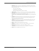
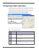
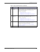
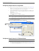
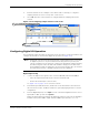
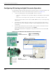
Table Of Contents
- RK-5409-5 Reference Kit for 916 MHz MeshScape™ Systems
- Contents
- About This Guide
- 1: Introduction
- 2: Installing the MeshScape System
- 3: Running MeshScape Network Monitor
- MeshScape Network Monitor Overview
- Configuring a Node’s Operation
- Configuring Sample Interval of Single Node
- Configuring Sample Interval of all Network Nodes
- Configuring Digital I/O Operation
- Configuring UART Operation
- Configuring AD (analog-to-digital) Converter Operation
- Configuring RS-232 Operation (MN-5409 only)
- Configuring RS-485 Operation (MN-5409 only)
- Using Watch Function to Display Configuration Information
- Labeling an End Node or Mesh Node
- Configuring Persistence Attributes
- Selecting a Com Port on the Host PC
- Configuring Serial and ADC Data Formats
- Turning Event Tracking On/Off
- Broadcasting Data to All Nodes.
- Creating an Event Log File
- Viewing the Contents of an Event Log File
- Viewing MeshScape Statistics
- 4: Using the MeshScape API
- A: Sample Application
- B: Performing Firmware Upgrades and Configuring Device IDs
- Glossary
- Index

RK-5409-5 Reference Kit User’s Guide 3-7
Configuring a Node’s Operation
E Serial Data
Config
This panel is used to select a serial I/O operation for a device: Digital
UART, RS-232 (MN-5409 only), or RS-485 (MN-5409 only). Selecting
serial operation disables digital I/O functionality because these
operations share the same pins.
For details, see the following:
• ’Configuring UART Operation’ on page 3-12
• ’Configuring RS-232 Operation (MN-5409 only)’ on page 3-15
• ’Configuring RS-485 Operation (MN-5409 only)’ on page 3-16
F Serial Data
Out
This panel, which is only used if the node is configured for serial
operation, is used to send serial data to the node.
For details, see the following:
• ’Configuring UART Operation’ on page 3-12
• ’Configuring RS-232 Operation (MN-5409 only)’ on page 3-15
• ’Configuring RS-485 Operation (MN-5409 only)’ on page 3-16
G Watch This option opens a new widow that displays information relating to the
the node’s various interfaces, including analog and digital I/O
configuration states and packets received/sent.
For details, see ’Using Watch Function to Display Configuration
Information’ on page 3-17
H Update Updates the selected device with any changes made to its configuration.
Table 3-6. Device window functions (continued)
Item Description Function