
User Manual
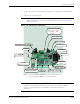
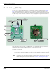
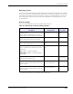
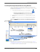

Table Of Contents
- RK-5409-5 Reference Kit for 916 MHz MeshScape™ Systems
- Contents
- About This Guide
- 1: Introduction
- 2: Installing the MeshScape System
- 3: Running MeshScape Network Monitor
- MeshScape Network Monitor Overview
- Configuring a Node’s Operation
- Configuring Sample Interval of Single Node
- Configuring Sample Interval of all Network Nodes
- Configuring Digital I/O Operation
- Configuring UART Operation
- Configuring AD (analog-to-digital) Converter Operation
- Configuring RS-232 Operation (MN-5409 only)
- Configuring RS-485 Operation (MN-5409 only)
- Using Watch Function to Display Configuration Information
- Labeling an End Node or Mesh Node
- Configuring Persistence Attributes
- Selecting a Com Port on the Host PC
- Configuring Serial and ADC Data Formats
- Turning Event Tracking On/Off
- Broadcasting Data to All Nodes.
- Creating an Event Log File
- Viewing the Contents of an Event Log File
- Viewing MeshScape Statistics
- 4: Using the MeshScape API
- A: Sample Application
- B: Performing Firmware Upgrades and Configuring Device IDs
- Glossary
- Index

RK-5409-5 Reference Kit User’s Guide 2-13
Installing the Hardware
Mounting options
A 2-inch x 2-inch plastic housing is supplied with each end node and terminal board. You may
operate the end node installed within its housing while it is resting on a desktop or mounted to
a wall. When mounting the end node housing to a wall, we recommend that you secure it in
place using two #6 screws and screw anchors (not supplied) of the appropriate type for the
mounting surface.
Default settings
Table 2-5 lists the default settings for the MeshScape end node.
* Persisted indicates value is retained after off/on power cycle.
Table 2-5. MeshScape end node default settings
Variable
Description
Default Value Persisted?*
Sampling Interval
Defines the time interval between successive
sensor samples sent from End node to MeshGate
10 Seconds No
A/D Converter setup
Defines state of A/D converter sensor inputs
Channels 0-3 disabled No
DIO Setup
Defines state of digital I/O lines
DIO<0:3> configured as
inputs
No
Serial Data configuration
Defines configuration of serial data sensor input,
options are:
Off - DIO<0:3> configured as I/O lines
Digital UART - DIO<0:3> configured as digital
UART signals
Off - DIO<0:3> defined as I/O
lines
No
Label
Text label used to describe sensor
<blank> Yes
(on PC where
Monitor runs)
Group ID
Network ID used to identify members of the same
wireless network
Pre-programmed
User re-programmable
Yes
Device ID
Device ID used to uniquely identify each node in a
wireless network
Pre-programmed
User re-programmable
Yes