
User Manual
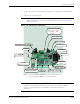
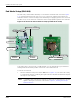
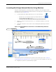

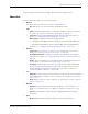
Table Of Contents
- RK-5409-5 Reference Kit for 916 MHz MeshScape™ Systems
- Contents
- About This Guide
- 1: Introduction
- 2: Installing the MeshScape System
- 3: Running MeshScape Network Monitor
- MeshScape Network Monitor Overview
- Configuring a Node’s Operation
- Configuring Sample Interval of Single Node
- Configuring Sample Interval of all Network Nodes
- Configuring Digital I/O Operation
- Configuring UART Operation
- Configuring AD (analog-to-digital) Converter Operation
- Configuring RS-232 Operation (MN-5409 only)
- Configuring RS-485 Operation (MN-5409 only)
- Using Watch Function to Display Configuration Information
- Labeling an End Node or Mesh Node
- Configuring Persistence Attributes
- Selecting a Com Port on the Host PC
- Configuring Serial and ADC Data Formats
- Turning Event Tracking On/Off
- Broadcasting Data to All Nodes.
- Creating an Event Log File
- Viewing the Contents of an Event Log File
- Viewing MeshScape Statistics
- 4: Using the MeshScape API
- A: Sample Application
- B: Performing Firmware Upgrades and Configuring Device IDs
- Glossary
- Index

2-12 Millennial Net
Installing the MeshScape System
End Node Setup (EN-5409)
The end nodes, model number EN-5409, are mounted to terminal boards as shown in Figure
2-10. A terminal board provides easy access to I/O connections and the power switch. The
terminal board also contains a battery holder and battery for supplying power to the end node.
The label on top of the end node contains the device and group IDs assigned to the end node.
Figure 2-10. End node and terminal board (top and bottom views)
To provide power to the end node, a 3 VDC lithium coin cell (CR2032 type) is provided and
already installed in the battery holder on the back of the terminal board.
To activate an end node:
• Turn the terminal board's power switch ON (refer to Figure 2-10). The end node is ready
to communicate directly or indirectly (through an mesh node) with the MeshGate. Repeat
this step for each end node.
Note:
C
Configuring and connecting an end node or mesh node to external devices via their
digital or analog I/O connectors is discussed in
Chapter 3, “Running MeshScape
Network Monitor”.
End Node
Terminal Board
3 VDC Lithium Coin Cell
Lithium Coin Cell Holder
Digital I/O
Ter minals
Power Switch
ON/OFF
Analog I/O
Terminals
Group ID
Device ID
(P1) Battery Connector