
User Manual
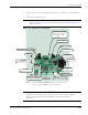
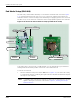
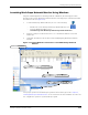

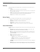
Table Of Contents
- RK-5409-5 Reference Kit for 916 MHz MeshScape™ Systems
- Contents
- About This Guide
- 1: Introduction
- 2: Installing the MeshScape System
- 3: Running MeshScape Network Monitor
- MeshScape Network Monitor Overview
- Configuring a Node’s Operation
- Configuring Sample Interval of Single Node
- Configuring Sample Interval of all Network Nodes
- Configuring Digital I/O Operation
- Configuring UART Operation
- Configuring AD (analog-to-digital) Converter Operation
- Configuring RS-232 Operation (MN-5409 only)
- Configuring RS-485 Operation (MN-5409 only)
- Using Watch Function to Display Configuration Information
- Labeling an End Node or Mesh Node
- Configuring Persistence Attributes
- Selecting a Com Port on the Host PC
- Configuring Serial and ADC Data Formats
- Turning Event Tracking On/Off
- Broadcasting Data to All Nodes.
- Creating an Event Log File
- Viewing the Contents of an Event Log File
- Viewing MeshScape Statistics
- 4: Using the MeshScape API
- A: Sample Application
- B: Performing Firmware Upgrades and Configuring Device IDs
- Glossary
- Index

RK-5409-5 Reference Kit User’s Guide 2-11
Installing the Hardware
1. Remove the four cover screws that secure the top cover to the base as shown in Figure
2-8.
2. Lift the top cover off the base.
Figure 2-9. Mesh node components
Note:
C
Configuring and connecting an end node or mesh node to external devices via their
digital or analog I/O connectors is discussed in
Chapter 3, “Running MeshScape
Network Monitor”.
Caution
A jumper is factory-installed on JP1 that connects pins 2 and 3 together. Do not
remove or change the position of this jumper as it will cause the device to
malfunction.
REV-SMA Antenna Connector
(SL1) Power Connector
Battery or AC Adapter
Pin 1(right): GND
Pin 2(left): +
Notes: 1. Callouts for SL1–8 and RS-485 point to pin 1 of each connector
2. Connectors labeled as N/A are reserved for future use.
Power Jack (N/A)
Power Switch
ON/OFF
RS-232 Port
LED 1 (Online)
LED 2 (RF Activity)
RS-485 Connector
(SL5) UART Connector
(SL3) DIO
Digital I/O Connector
(SL8) N/A
(SL7) External Firmware
& ID Programming
(SL4) ADC
A/D Converter Connector
(SL2) N/A
(JP1) Jumper
Pins 2 & 3 jumped
(SL6) N/A