
User Manual
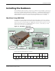
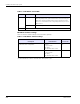
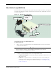
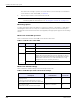
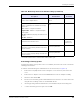
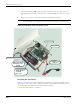
Table Of Contents
- RK-5409-5 Reference Kit for 916 MHz MeshScape™ Systems
- Contents
- About This Guide
- 1: Introduction
- 2: Installing the MeshScape System
- 3: Running MeshScape Network Monitor
- MeshScape Network Monitor Overview
- Configuring a Node’s Operation
- Configuring Sample Interval of Single Node
- Configuring Sample Interval of all Network Nodes
- Configuring Digital I/O Operation
- Configuring UART Operation
- Configuring AD (analog-to-digital) Converter Operation
- Configuring RS-232 Operation (MN-5409 only)
- Configuring RS-485 Operation (MN-5409 only)
- Using Watch Function to Display Configuration Information
- Labeling an End Node or Mesh Node
- Configuring Persistence Attributes
- Selecting a Com Port on the Host PC
- Configuring Serial and ADC Data Formats
- Turning Event Tracking On/Off
- Broadcasting Data to All Nodes.
- Creating an Event Log File
- Viewing the Contents of an Event Log File
- Viewing MeshScape Statistics
- 4: Using the MeshScape API
- A: Sample Application
- B: Performing Firmware Upgrades and Configuring Device IDs
- Glossary
- Index

RK-5409-5 Reference Kit User’s Guide 2-9
Installing the Hardware
* Persisted indicates value is retained after off/on power cycle.
Converting to battery power
For applications where an AC power source is not available, the mesh node can be converted to
a battery powered device.
To install an internal battery pack and batteries into an mesh node (see Figure 2-8):
1. Remove the four philips head screws securing the cover to the base, then remove the
cover.
2. Remove the AC adapter connector from SL1 and remove the AC adapter assembly.
3. Turn the Power Switch OFF.
4. Mount one of the battery packs included with the kit to the back cover of the mesh node
using the two mounting screws also included with the kit.
5. Observing polarity, install two AA batteries (not included in kit) into the battery pack.
6. Connect the battery pack to keyed connector SL1.
DIO Setup
Defines state of digital I/O lines
DIO<0:3> configured as
inputs
No
Serial Data configuration
Defines configuration of serial data sensor input,
options are:
Off - DIO<0:3> configured as I/O lines
Digital UART - DIO<0:3> configured as digital
UART signals
RS-232 - 9600 baud, No parity, No hardware flow
control
RS-485 - 9600 baud
Off - DIO<0:3> defined as I/O
lines
No
Label
Text label used to describe sensor
<blank> Yes
(on Network
Monitor host)
Group ID
Network ID used to identify members of the same
wireless network
Pre-programmed
User re-programmable
Yes
Device ID
Device ID used to uniquely identify each node in a
wireless network
Pre-programmed
User re-programmable
Yes
Table 2-4. MeshScape mesh node default settings (continued)
Variable
Description
Default Value Persisted?*