
User Manual
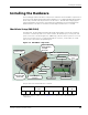
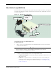
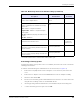
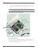
Table Of Contents
- RK-5409-5 Reference Kit for 916 MHz MeshScape™ Systems
- Contents
- About This Guide
- 1: Introduction
- 2: Installing the MeshScape System
- 3: Running MeshScape Network Monitor
- MeshScape Network Monitor Overview
- Configuring a Node’s Operation
- Configuring Sample Interval of Single Node
- Configuring Sample Interval of all Network Nodes
- Configuring Digital I/O Operation
- Configuring UART Operation
- Configuring AD (analog-to-digital) Converter Operation
- Configuring RS-232 Operation (MN-5409 only)
- Configuring RS-485 Operation (MN-5409 only)
- Using Watch Function to Display Configuration Information
- Labeling an End Node or Mesh Node
- Configuring Persistence Attributes
- Selecting a Com Port on the Host PC
- Configuring Serial and ADC Data Formats
- Turning Event Tracking On/Off
- Broadcasting Data to All Nodes.
- Creating an Event Log File
- Viewing the Contents of an Event Log File
- Viewing MeshScape Statistics
- 4: Using the MeshScape API
- A: Sample Application
- B: Performing Firmware Upgrades and Configuring Device IDs
- Glossary
- Index

RK-5409-5 Reference Kit User’s Guide 2-3
Installing the Hardware
Installing the Hardware
The following procedures describe in order, how to install the various hardware components of
the reference kit. When initially setting up the hardware, it is recommended that the MeshGate,
mesh nodes, and end nodes be placed close to the host PC. This will make verifying proper
network installation and operation easier when first establishing a session with MeshScape
Network Monitor. The devices can then be moved away from the host PC as needed.
MeshGate Setup (MG-5409)
The MeshGate, model number MG-5409 (label with model number on bottom), is shipped
enclosed in a case that provides access to the antenna, RS-232 data port, console port, and
power connectors as shown in
Figure 2-5. Additionally, a lift-off connector panel access cover
on the case provides access to a 12-pin terminal block connector, a reset button, an on/off
switch, and a 6-pin external programming port.
Figure 2-5. MeshGate components
The pin-out for the terminal block is as follows:
During the setup procedure, refer to Figure 2-5 for location of the various MeshGate
components.
RS-485 PWR
OUT
RS-232 PWR
IN
RTN A B 3.3V GND RTS CTS RX TX GND +
REV-SMA Antenna Connector
Power Adapter
Connector
External
Programming
Port
Power LED
RF Activity LED
Status LED
RS-232 Port
Terminal Block
Product Label with:
- Model Number
- GroupID
- Device ID
Console Port
Connector Panel
Access Cover
Reset Button
On/Off Switch