
User Manual
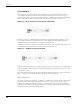
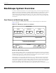
Table Of Contents
- RK-5409-5 Reference Kit for 916 MHz MeshScape™ Systems
- Contents
- About This Guide
- 1: Introduction
- 2: Installing the MeshScape System
- 3: Running MeshScape Network Monitor
- MeshScape Network Monitor Overview
- Configuring a Node’s Operation
- Configuring Sample Interval of Single Node
- Configuring Sample Interval of all Network Nodes
- Configuring Digital I/O Operation
- Configuring UART Operation
- Configuring AD (analog-to-digital) Converter Operation
- Configuring RS-232 Operation (MN-5409 only)
- Configuring RS-485 Operation (MN-5409 only)
- Using Watch Function to Display Configuration Information
- Labeling an End Node or Mesh Node
- Configuring Persistence Attributes
- Selecting a Com Port on the Host PC
- Configuring Serial and ADC Data Formats
- Turning Event Tracking On/Off
- Broadcasting Data to All Nodes.
- Creating an Event Log File
- Viewing the Contents of an Event Log File
- Viewing MeshScape Statistics
- 4: Using the MeshScape API
- A: Sample Application
- B: Performing Firmware Upgrades and Configuring Device IDs
- Glossary
- Index

RK-5409-5 Reference Kit User’s Guide 1-11
The MeshScape RK-5409-5 Reference Kit
Major Features
Major features of the MeshScape RK-5409-5 Reference Kit include the following:
• Frequency band: 916 MHz
• Bi-directional/multiple-access communication
• MeshScape Network Monitor graphical user interface (GUI) for configuring the
MeshScape system and evaluating its performance
• Application Programming Interface (API)
• End node and mesh node-specific features include:
– configurable sampling interval
– digital I/O - 4 channels
– ADC input - 4 channels
– UART input/output
Reference Kit Contents
The MeshScape RK-5409-5 Reference Kit contains the following components:
• (5) EN-5409 end nodes; each end node is mounted to a terminal board containing a
battery. A 2-inch x 2-inch plastic housing is supplied for each end node.
• (3) MN-5409 Mesh Nodes (enclosed) with attached AC power adapters.
• (1) MG-5409 MeshGate gateway (enclosed) with an attached AC power adapter.
• (4) Antennas; one 1/2-wave antenna for each Mesh Node and one for the MeshGate.
• (3) Battery packs; one for each Mesh Node. Each battery pack requires two AA batteries
(not included).
• (1) RS-232 serial cable for connecting the MeshGate serial port to the host PC. This is a
DB-9, male-to-female, straight-through cable.
• (1) RS-232 serial cable for connecting the MeshGate console port to the host PC. This is a
DB-9-to-mini-connector cable.
• (1) Temperature sensor assembly (for sample EN-5409 application). The enclosed
temperature sensor assembly contains a terminal board (no End Node) and a battery.
• (1) CD-ROM containing support documentation and application software, including the
MeshScape Network Monitor program, MeshScape Programmer application, and API
software.