
User Manual

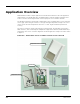
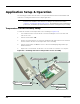
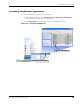
Table Of Contents
- RK-5409-5 Reference Kit for 916 MHz MeshScape™ Systems
- Contents
- About This Guide
- 1: Introduction
- 2: Installing the MeshScape System
- 3: Running MeshScape Network Monitor
- MeshScape Network Monitor Overview
- Configuring a Node’s Operation
- Configuring Sample Interval of Single Node
- Configuring Sample Interval of all Network Nodes
- Configuring Digital I/O Operation
- Configuring UART Operation
- Configuring AD (analog-to-digital) Converter Operation
- Configuring RS-232 Operation (MN-5409 only)
- Configuring RS-485 Operation (MN-5409 only)
- Using Watch Function to Display Configuration Information
- Labeling an End Node or Mesh Node
- Configuring Persistence Attributes
- Selecting a Com Port on the Host PC
- Configuring Serial and ADC Data Formats
- Turning Event Tracking On/Off
- Broadcasting Data to All Nodes.
- Creating an Event Log File
- Viewing the Contents of an Event Log File
- Viewing MeshScape Statistics
- 4: Using the MeshScape API
- A: Sample Application
- B: Performing Firmware Upgrades and Configuring Device IDs
- Glossary
- Index

A-4 Millennial Net
Application Setup & Operation
The following procedures describe how to set up the RK-5409-5 Reference Kit hardware and
software for creating the Reference Kit’s sample application.
Temperature Sensor Assembly Setup
To install an end node in the temperature sensor assembly (see Figure A-3):
1. Use an Allen wrench to turn in the two set screws holding the cover to the base and
remove the cover.
2. Turn the Power Switch OFF.
3. Remove an end node from one of the kit’s terminal boards and install it on the terminal
board located on the base of the temperature sensor assembly.
4. Turn the Power Switch to ON. The sensor is discovered and displayed by MeshScape
Network Monitor.
5. Replace the cover and back out the two cover set screws to secure the cover in place.
Figure A-3. Installing end node in temperature sensor assembly
Note:
Before this sample application can be executed, you must install the RK-5409
Reference Kit’s hardware and software according to the instructions found in
Chapter 2, “Installing the MeshScape System”. The MeshGate must be installed and
powered on, and MeshScape Network Monitor must be running before proceeding.
Install end node
3
Turn Power Switch ON
4
Turn Power Switch OFF
2
Replace cover
5
Turn in cover set screws (2),
1
then remove cover