
User's Manual
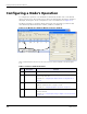
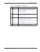
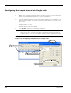
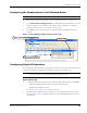
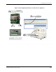
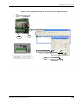
Table Of Contents
- MeshScape™ RK-5424-5 Reference Kit for 2.4 GHz MeshScape Systems User's Guide
- Contents
- About This Guide
- 1: Introduction
- 2: Installing the MeshScape System
- 3: Running MeshScape Network Monitor
- MeshScape Network Monitor Overview
- Configuring a Node’s Operation
- Labeling an End Node or Mesh Node
- Configuring Persistence Attributes
- Selecting a Com Port on the Host PC
- Configuring Serial and ADC Data Formats
- Turning Event Tracking On/Off
- Broadcasting Data to All Nodes.
- Creating an Event Log File
- Viewing the Contents of an Event Log File
- Viewing MeshScape Statistics
- 4: Using the MeshScape API
- A: Running the Demo Application
- B: Using MeshScape Programmer
- Glossary
- Index

3-14 Millennial Net
Running MeshScape Network Monitor
Configuring AD (analog-to-digital) Converter Operation
The following procedure describes the steps that need to be taken to set up the hardware and
configure an End Node or Mesh Node for AD Converter operation (see
Figure 3-16):
1. Connect 0–3 VDC signals to the following A/D Converter connectors:
– End Node: Connect signal source ground to GND_CPU (pin 1 on terminal block P10).
Pin 1 - Gnd
Pin 2 - AD0 (Input)
Pin 3 - AD1 (Input)
Pin 4 - AD2 (Input)
Pin 5 - AD3 (Input)
– Mesh Node: Connect signal source ground to terminal block connector Pin 11
(Ground).
Use any or all of the A/D Converter channels (AD0–AD3) for connecting analog signal
sources.
2. From MeshScape Network Monitor, double-click on the desired device from the list of
discovered sensor nodes. The Device window is opened, displaying the device’s current
configuration.
3. From the AD Converter panel, select the AD Converter channels to which the external
analog signals have been connected, then select Update.
MeshScape Network Monitor displays the analog information for the node in the
ADC0-3 column.
Note:
The input range of the analog inputs is 0 to V
DD
(power supply voltage).