
User's Manual
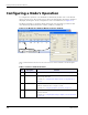
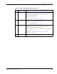
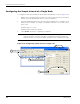
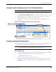
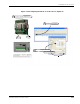
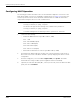
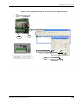
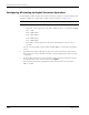
Table Of Contents
- MeshScape™ RK-5424-5 Reference Kit for 2.4 GHz MeshScape Systems User's Guide
- Contents
- About This Guide
- 1: Introduction
- 2: Installing the MeshScape System
- 3: Running MeshScape Network Monitor
- MeshScape Network Monitor Overview
- Configuring a Node’s Operation
- Labeling an End Node or Mesh Node
- Configuring Persistence Attributes
- Selecting a Com Port on the Host PC
- Configuring Serial and ADC Data Formats
- Turning Event Tracking On/Off
- Broadcasting Data to All Nodes.
- Creating an Event Log File
- Viewing the Contents of an Event Log File
- Viewing MeshScape Statistics
- 4: Using the MeshScape API
- A: Running the Demo Application
- B: Using MeshScape Programmer
- Glossary
- Index

RK-5424-5 Reference Kit User’s Guide 3-9
Configuring a Node’s Operation
Configuring the Sample Interval of all Network Nodes
To configure all the network nodes with the same sampling interval rate (see Figure 3-13):
1. Select Network>All Sampling Intervals. The Edit Sampling Interval window is opened.
2. Enter the interval rate as a multiple of 100 milliseconds. For example, to configure a
sampling interval rate of 20 seconds, enter a value of 200.
3. Select OK. All nodes on the network are configured with the sampling interval rate
entered.
Figure 3-13. Configuring sample interval of all nodes
Configuring Digital I/O Operation
The following procedure describes the steps that need to be taken to set up the hardware and
configure an End Node or Mesh Node for digital I/O operation (see
Figure 3-14).
Digital Input Setup
1. Connect the digital source signals to the connectors (DIO 0–DIO 3) and Ground (GND) of:
– End Node’s digital terminal block (P9 located on terminal board).
– Mesh Node’s terminal block pins.
See Figure 3-14 on page 3-11 for connector locations.
2. From MeshScape Network Monitor, double-click on the desired device from the list of
discovered sensor nodes. The Device window is opened, displaying the device’s current
configuration.
Note:
It can take a long time to change the sampling interval for all network nodes.
Note:
All Digital I/O contain on-board pull-up resistors. To optimize current consumption,
be sure to take into account the pullups when setting I/O values.
Select Network>All Sampling Intervals
1
Configure interval time
2
Select OK
3