
User's Manual
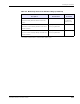
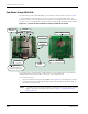
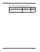
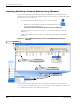
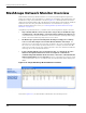
Table Of Contents
- MeshScape™ RK-5424-5 Reference Kit for 2.4 GHz MeshScape Systems User's Guide
- Contents
- About This Guide
- 1: Introduction
- 2: Installing the MeshScape System
- 3: Running MeshScape Network Monitor
- MeshScape Network Monitor Overview
- Configuring a Node’s Operation
- Labeling an End Node or Mesh Node
- Configuring Persistence Attributes
- Selecting a Com Port on the Host PC
- Configuring Serial and ADC Data Formats
- Turning Event Tracking On/Off
- Broadcasting Data to All Nodes.
- Creating an Event Log File
- Viewing the Contents of an Event Log File
- Viewing MeshScape Statistics
- 4: Using the MeshScape API
- A: Running the Demo Application
- B: Using MeshScape Programmer
- Glossary
- Index

RK-5424-5 Reference Kit User’s Guide 2-13
Installing the Hardware
Jumper settings
Note the following jumper settings on the end node terminal board:
• P6 - Install a jumper across P6 to enable the terminal board’s LEDs as follows:
– LED1 indicates power on/off.
– LED12 indicates the end node has a primary parent.
– LED2 indicates the end node has a secondary parent.
– LED3 – 6 & 10,11,13,14 indicate the state of their respective port (For example, if
the end node is configured in UART mode, LED4 will be active when receiving data
(RX line).
• P14 is used to connect the RS-232 transceiver’s I/O pins to the end node’s UART. Jumpers
must be engaged to use the end node’s RS-232 interface. To use the RS-232 transceiver, it
must be enabled by populating R6 with a 1K resistor and depopulating R19.
Default settings
Table 2-7 lists the default settings for the MeshScape end node.
Table 2-7. MeshScape end node default settings
Variable
Description Default Value Persisted?*
Sampling Interval
Defines the time interval between successive
sensor samples sent from end node to MeshGate
10 Seconds No
A/D Converter setup
Defines state of A/D converter sensor inputs
Channels 0-3 disabled Yes
DIO Setup
Defines state of digital I/O lines
DIO<0:3> configured as
inputs
Yes
Serial Data configuration
Defines configuration of serial data sensor input,
options are:
Off - DIO<0:3> configured as I/O lines
Digital UART - DIO<0:3> configured as digital
UART signals
Off - DIO<0:3> defined as I/O
lines
Yes
Label
Text label used to describe sensor
<blank> Yes
(on Network
Monitor host)
Group ID
Network ID used to identify members of the same
wireless network
Pre-programmed
User re-programmable
Yes