
User's Manual
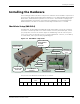
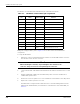
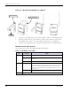
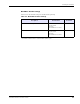
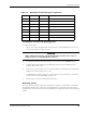
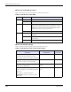
Table Of Contents
- MeshScape™ RK-5424-5 Reference Kit for 2.4 GHz MeshScape Systems User's Guide
- Contents
- About This Guide
- 1: Introduction
- 2: Installing the MeshScape System
- 3: Running MeshScape Network Monitor
- MeshScape Network Monitor Overview
- Configuring a Node’s Operation
- Labeling an End Node or Mesh Node
- Configuring Persistence Attributes
- Selecting a Com Port on the Host PC
- Configuring Serial and ADC Data Formats
- Turning Event Tracking On/Off
- Broadcasting Data to All Nodes.
- Creating an Event Log File
- Viewing the Contents of an Event Log File
- Viewing MeshScape Statistics
- 4: Using the MeshScape API
- A: Running the Demo Application
- B: Using MeshScape Programmer
- Glossary
- Index

2-10 Millennial Net
Installing the MeshScape System
Mesh node status LED operation
Table 2-5 describes how the status LEDs on the Mesh Node behave.
Mesh node default settings
Table 2-6 lists the default settings for the MeshScape mesh node.
Table 2-5. Mesh node status LEDs
LED Led State Status
PWR On Power on.
Off No power.
RF Activity Flashing Mesh Node detects RF activity. The RF Activity LED will flash
when detecting valid packets (packets destined for device)
and may also flash when detecting invalid packets (packets
destined for other devices) or environmental noise. Only
valid packets are processed by the device.
Off No RF activity detected.
STS On The Mesh Node has established two northbound pathways to the
MeshGate.
Blinking The Mesh Node has established a single northbound pathway to
the MeshGate.
Off The Mesh Node is not on the MeshScape network.
Table 2-6. MeshScape mesh node default settings
Variable
Description Default Value Persisted?*
Sampling Interval
Defines the time interval between successive
sensor samples sent from mesh node to MeshGate
300 Seconds No
A/D Converter Setup
Defines state of A/D converter sensor inputs
Channels 0-3 disabled Yes
DIO Setup
Defines state of digital I/O lines
DIO<0:3> configured as
inputs
Yes
Serial Data configuration
Defines configuration of serial data sensor input,
options are:
Off - DIO<0:3> configured as I/O lines
Digital UART - DIO<0:3> configured as digital
UART signals
Off - DIO<0:3> defined as I/O
lines
Yes